Member since 09-Aug-1997

Build Type:
- Plank-on-frame
- Scratch
Country: Portugal
Era: 1815-1914
Length Range: 040-80 feet (12-24m)
Model Material: Wood
Model Type: Static
Propulsion Type: Impeller→ {Pole/Oar+Sail}
Scale: 1:40
Subject Type: Vessel→ Merchant→ Cargo→ Break-Bulk
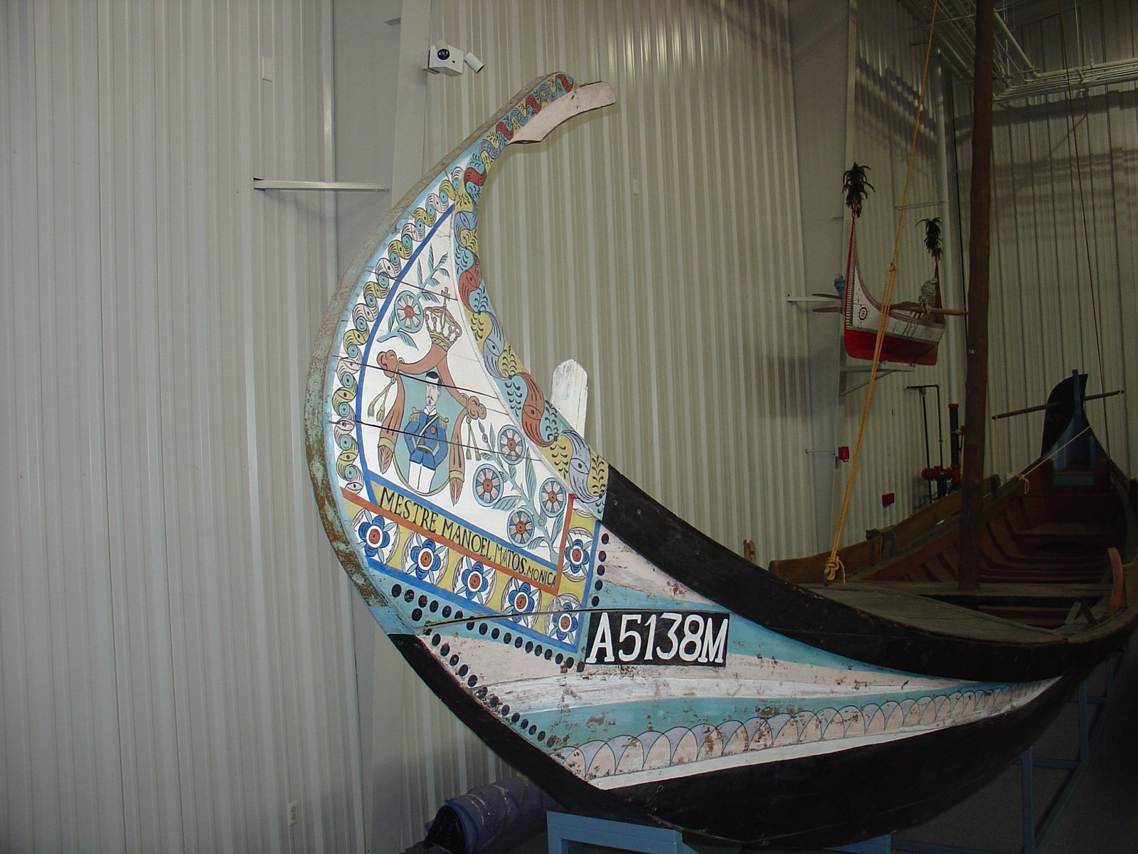
Culé
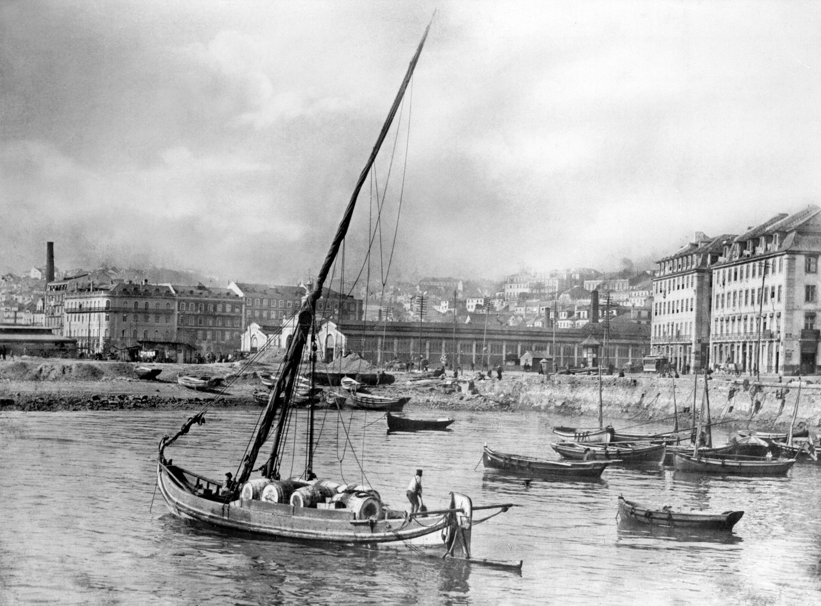
A culé is a cargo boat once used to carry salt, fruit, and other items to supply the city of Lisbon (Portugal), which sits on the wide estuary of the Rio Tejo (Tagus River). It was in use until the beginning of the twentieth century.
It is also known as a “Barco de água Acima”, which roughly translates to “boat of the upper river”. Having a wide, flat bottom and a long, shallow rudder, the boat could navigate the shallow waters of canals and the upper reaches of the Tejo.
Chata
The name of this boat type is derived from the word chato, which means flat. The flat bottom of these boats made them popular for pulling onshore and as tenders for larger shallow-draft boats (such as the culé).
Where appropriate, I have listed the source of the information within brackets. If it is “FMN” followed by a name, this is the username of an individual on Forum de Modelismo Nautico, a Portuguese modeling forum, where I have started a discussion on the culé.
Descriptions
Traffic [cargo] boat on the Tagus River, sailed until the beginning of the 20th century. Flat-bottomed, it had a wide-door rudder that steered by means of a stick called a “xarolo” to be able to go upriver and navigate shallow waters. It transported fruits and other foodstuffs to supply Lisbon
Google translation of text below
Barco de tráfego do rio Tejo, navegou até princípios do século XX. De fundo chato, possuía um leme de larga porta que governava por meio de uma vara chamada “xarolo”, para poder subir o rio e navagarem águas pouco profundas. Transportava frutas e outros víveres para abastecimento de Lisboa.
Instruction sheet from set of plans
Also known as varino de pau de aresta, since the bulwarks are joined at the stern by paus de aresta (cant planks), these boats had a large rudder with a long tiller that was in line with the bottom.
They could have one or two stays. The first one – carrying an extra sail – was used for lowering the single mast, which raked backwards, whenever necessary, and was rigged with a triangular lateen sail.
Usually they were 12 to 13m long with a crew of two men
Embarcações Regionais Da Tradição Portuguese (Regional Boats in the Portuguese Tradition) by Telmo Gomes – translation given in the text
Embarcação também chamada “varino de pau de aresta”, pois os remates dos costados com o fundo fazem-se por intermédio dos “paus de aresta”.
Motava grande leme de pá longa que alinhava pelo fundo. Apresentava um ou dois estais, destinando-se o primeiro – que enverga uma vela adicional – a fazer baixar quando necessário, o único mastro, muito inclinado para ré. Armava um latino triangular.
Normalmente com 12 a 13 metros de comprimento, tinha uma tripulação dois homens
Embarcações Regionais Da Tradição Portuguese (Regional Boats in the Portuguese Tradition) by Telmo Gomes
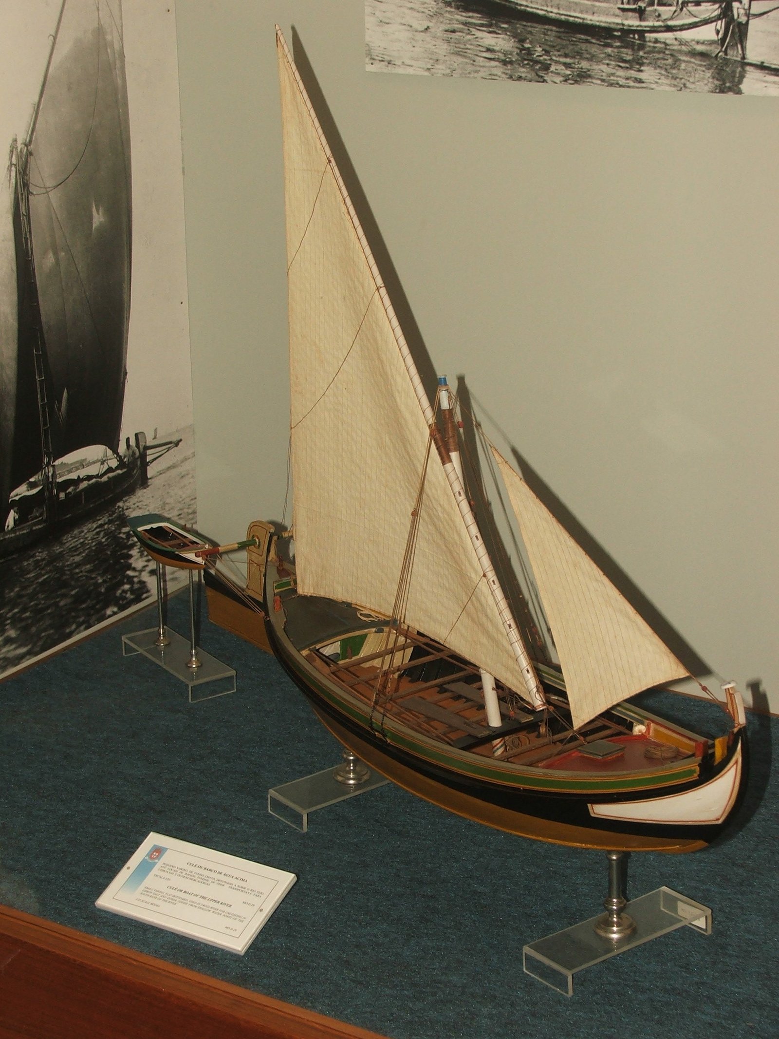
Culé or Boat of the Upper River
English-text placard for model in the Museu de Marinha, Lisbon, Portugal
Small varino, flat-bottomed, used in Tagus River for unloading in Lisbon salt and other goods from shallow water ports of the south bank of the river.
Culé ou Barco de água Acima
Portuguese-text placard for model in the Museu de Marinha, Lisbon, Portugal
Pequeno varino, de fundo chato, destinado a subir o Rio Tejo até locais de baixos fundos, de onde transportava para Lisboa sal e outras mercadorias
Culé Portugal, central: Flat-bottomed cargo vessel that brought produce, cork, grain, and passengers from the shallow upper waterways of the Tagus Estuary to the Lisbon area. Double-ended; bottom swept up at the ends, the bow curving up smoothly to a slightly recurved ornamental stemhead, the stern rounding up more vertically. Shallow rudder, wide-bladed below the waterline, narrower above, terminating in a tall rudderhead; tiller worked by block and tackle from a horizontal peg run through the top of the rudder. Leeboards used while sailing. Lateen sail set to an aft-raking mast. One or 2 headsails. Average 30t, some to 100t. Other recorded names: colé, monaio.
Aak to Zumbra, the Mariners’ Museum
Books and Articles
Barcos do Tejo – A fragata do Tejo e tipos relacionados
Tagus boats – The Tagus frigata and related types
The most helpful of all Forum de Modelismo Nautico members (username ‘pjesus’) is someone I now consider a friend. Having difficulty reaching the Museu de Marinha directly, I asked if he would enquire about the cost to purchase and ship this book, which is/was offered by the museum. Instead of a reply, the book arrived at my door! He refused reimbursement. I’ll be happy to repay with a gift or favor when the opportunity arises. The culé is not related to the frigata, but I hoped some culés might appear in photographs where the frigata and its cousins were the primary subjects. There was also a chance that some of the construction details would be common. Even if nothing could be gleaned from the book, I knew it would be interesting. It turned out to be most helpful in regards to the way the lateen yard is secured to the mast – details of which were not included in the plans. References to this book are found in other sections of this page.

Tagus River Barges and Passenger Carriers
This article by John M. Kochiss appeared in the The Mariner’s Mirror, Volume 64, 1978, Issue 2. As in the book above, Mr. Kochiss focuses on the fragata and its related type. Deeper into the article, on page 180, he mentions the transom-sterned varino and the double-ended culé:
The most obvious varino characteristic when afloat is its gracefully curved bow that some bargemen claim has Phoenician origin. Formed in a curious way, the stem sweeps up from the bottom in a near semi-circle terminating inboard and pointing aft. […] This kind of bow is not unique to the varino for it is seen on other flat-bottom Portuguese craft such as the moliceiros or seaweed boats or [sic] Aveiro.
The culé or colé was the double-ended version of the varino. It averaged about 30 tones capacity though some reached as high as 100 tones. They were rigged with a single lateen sail and one or two head sails. The stern configuration, and more specifically the steering, set it apart from the varino and indeed from all other barges. A block and tackle pair rather than a tiller or wheel manipulated the long shallow rudder. A tube or pipe pierced the rudderhead face at a right angle. Through this ran a wood spar which was allowed, I think, to slide in and out permitting it to be unequal and proportionate to the stress or pull placed upon it by the block and tackle fixed at each end and to the hull. The helmsman moved the rudder by handling the falls on each side of the rudder.
The culé worked higher up the river than the varino. here it picked up salt, fruit, grains, cork, provisions, and passengers. Up river where the wind might be scarce the culé was poled or punted in the same way, in fact, as the barges of today. Two long poles for this purpose, and for fending off, are still standard equipment on all barges. With favourable winds they sailed and whenever possible leeboard were employed.
Two things of note in this article were missed until after the model was complete. The first is a pipe acting as sleeve and perhaps reinforcing the rudder where the pole penetrates it. I’m not certain of it being free to move athwartships, but the sleeve itself seems probable and in retrospect, I would have included it.
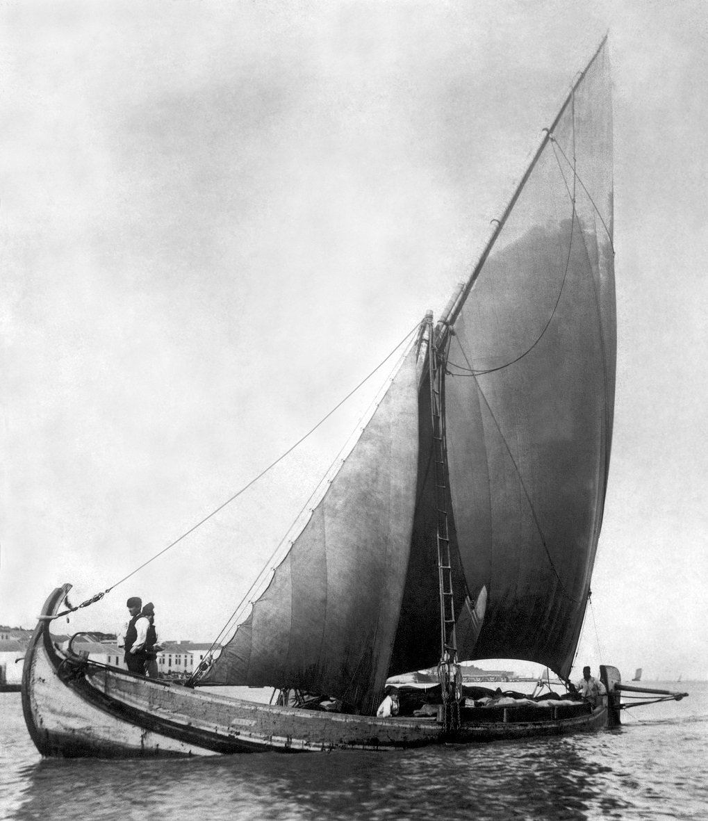
The second is the mention of leeboards, which are also noted elsewhere. Having decided to show the vessel at rest, with sails furled, I would have at most shown the leeboards stowed. However, I could not find any details of how these leeboards would have been constructed or where they would have been affixed. Also, I did not know by what means they would have been mounted, that is, if any permanent fixtures on the side of the hull should have been included. There is one photo below that shows a culé under sail with no leeboard visible, so I am not overly concerned about omitting them.
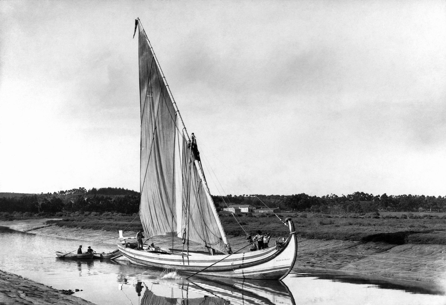
The photograph of Flor do Tejo appears in this article, but my higher-resolution copy came from another source.
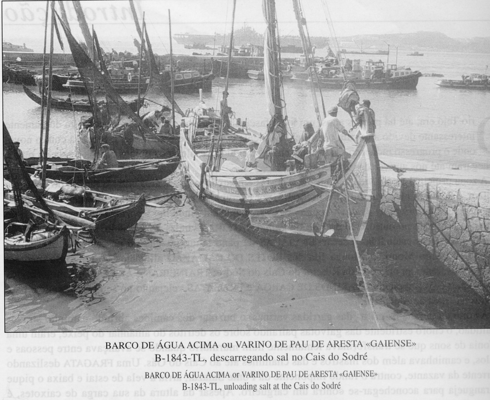
Photographs
Because they are so similar, the photographs that follow include both culés and varinos. Except as noted, I unfortunately misplaced my records of where on the internet these photos were found.
Note that this boat either has no foredeck or a much shallower forward cabin.
Oddly, this is the cover photo for Barcos do Tejo, which due to fundamental differences in the hull construction, does not include the culé as a “related type”.
Note that this shows two jib stays.
The descriptions at the beginning of this page note that one or two were used.
The plans I used show only one.
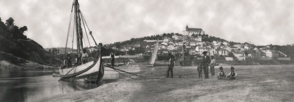
Found on Portos do Tejo e Barcos d’Água Acima by António Matias Coelho
Photo credit: Photographic Archive of the Municipality of Constância
Images
As with the photographs, I misplaced my records of where on the internet these images were found.
Note the lee boards.
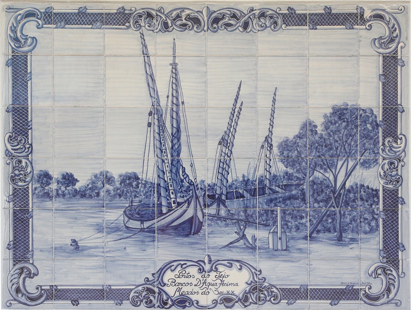
Found on the web page Portos do Tejo e Barcos d’Água Acima” by António Matias Coelho
Photograph by António Matias Coelho
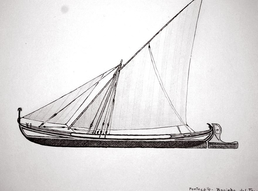
Portogallo is Italian for Portugal. Would “barinho” be the Italian spelling of varino? The vessel is clearly a culé.
The skeg on the stern is probably a mistake by the artist.
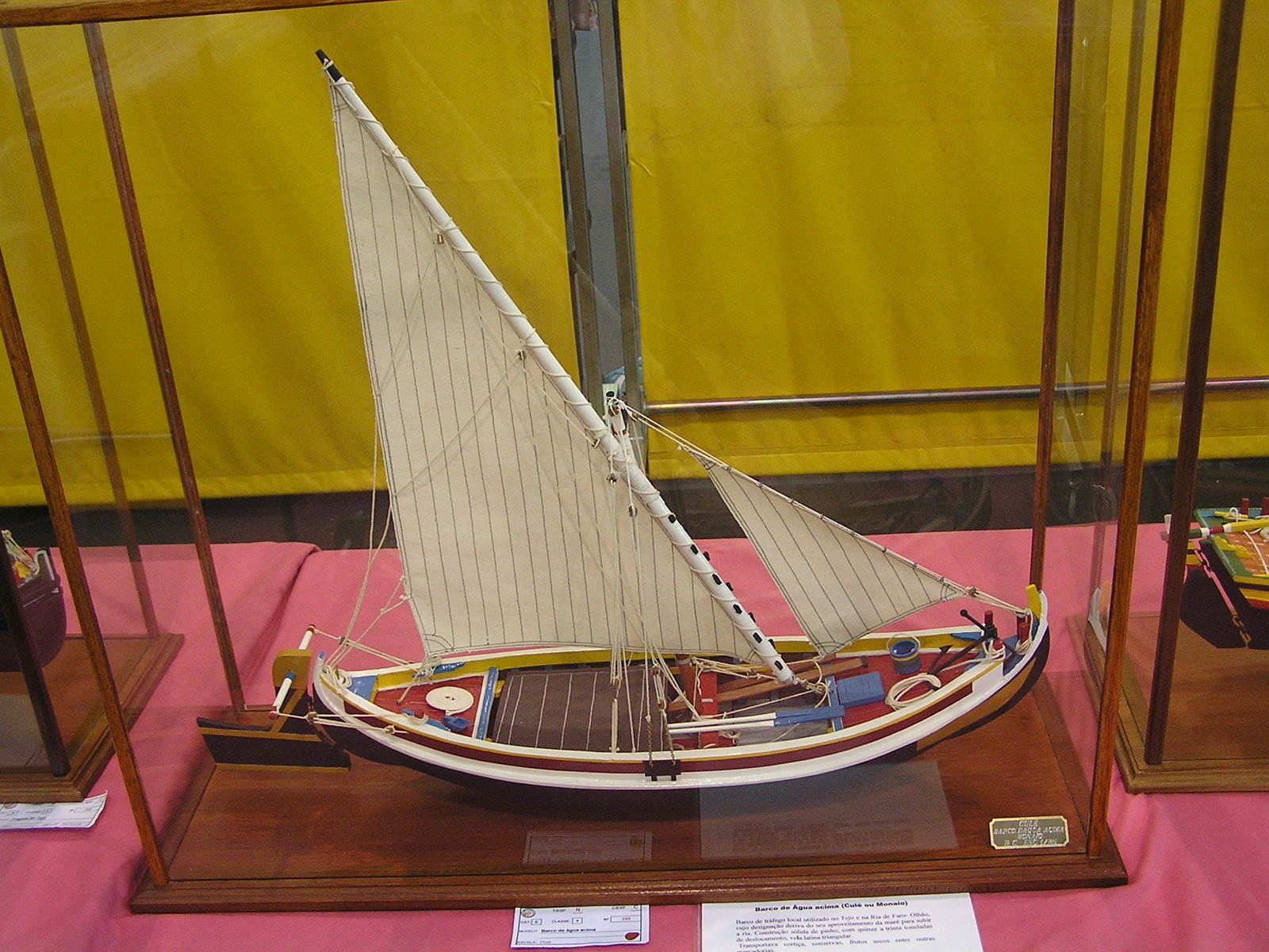
Other Models
Plans
Plans were purchased at the Museu de Marinha, in Lisbon. The museum is fantastic and well worth going out of your way to visit! Do yourself a favor and allow more time than I had available during our cruise ship’s brief stop. As for the city itself, what little I was able to visit after leaving the museum left me wanting to return to see more.
What follows are notes on the contents of the plans, but in order to avoid copyright issues. I did not include the plans themselves (well, just a small snippet or two).
Cover Sheet
- barco de Agua Acima
-
Literally, “of water above”. The meaning is ‘upriver’ or ‘upstream’. In other words, the rivers origin, where it is still shallow. This is the reason that the rudder is very large and is long instead of deep. [FMN-skipper]
- culé
-
A type of boat that was once used for fishing and later for transportation of goods. [FMN-pjesus]. Also see Descriptions.
- monaio
-
An alternate (perhaps regional or temporal) name for a culé. [FMN-pjesus, lmcharrua, skipper].
Also see Descriptions.
Palamenta e Utensilios
- azul
-
Blue
- balão
-
Literally, ‘balloon’. I believe this is a boat fender.
- balde de arrebem
-
Perhaps a bucket for drawing water from the river [FMN-skipper]
- balde de limpeza
-
Cleaning bucket [Google Translate]
- bancaça
-
Bench [Google Translate]. Bench fitted on top of the inwales. In the plans it is a simple rectangle with a black band in the middle, as shown in another sketch (see prancha). The black band shows that the cross section is rectangular and indicates the thickness [FMN-skipper]
- barril de alcartar
-
“Carrying Barrel” [Google Translate]. Drinking water?
- bomba de esgoto
-
Bilge pump

- branco
-
White
- croquet
-
Boat hook. In the drawing there is a black circle in the center of the handle, which indicates that the cross section is circular (more at prancha)
- encarnado
-

Literally, ‘flesh-colored’, but in meaning it is the same as red. As best as I can determine from web searches and the help of forum members, the Portuguese words for ‘red’ (vermelho) and ‘flesh-colored’ (encarnado) are not different shades. Forum member Felipe Seguro offered an rgb value for what he considers encarnado (237,28,36). It is slightly darker than pure red (255,0,0). [FMN-Paulo Simões,Filipe Seguro]
- fogareiro
-
Stove [Ricardo – a work associate]; confirmed much later by Google Translate.
- lambaz
-
Mop made of ropes and/or rags [ FMN-skipper]
- lantern
-
Lantern
- palamenta
-
Rigging, in the broadest sense of the word. One definition of rigging includes only the ropes, blocks and other objects used to support and operate the masts, booms, spars, and sails. Another valid definition of the word includes the latter. In un-masted boats the word rigging can reasonably be used to describe the oars, oarlocks, poles, boathooks, anchor, etc. In English one would generally refer to these items as ‘outfitting’. The Portuguese word ‘palamenta’ refers to all of the aforementioned objects. The English word ‘outfitting’ can also refer to items not covered by ‘palamenta’ (see ‘utensilios’, below) [FMN-skipper]
- picok
- See bomba de esgoto. This is the long vertical portion of the ‘bomba de esgoto’, or perhaps the plunger inside. The translation is uncertain, but it is not necessary as the function of the ‘bomba de esgota’ is obvious. I am told that a bilge pump handle is called a ‘picota’, and that perhaps ‘picok’ is a mispelling on the drawing. I wonder also if ‘picok’ might be an older or regional variation of ‘picota’. The sketch is a good approximation of the original drawing. [FMN-Artur Marques]
- podoa
-

My original guess was that this is a spigot (“a device used to control the flow of liquid from something such as a barrel”) perhaps for the barril-de-alcartar. Among the many kind offerings from the Fórum de Modelismo Náutico, I was informed that this is in fact a pruning knife that is mounted on a pole anywhere from 60cm to 2m long. Speculation is that it is for cutting vegetation along the river bank [FMN-skipper]. The sketch is roughly the same as the original drawing.

- prancha
-

Literally, ‘plate’. The meaning is ‘gangplank’. The ends are capped with metal to protect them from abrasion. [FMN-skipper] The sketch above is very close to how it appears in the drawing. The band represents the cross section of the plank, showing that it is rectangular and indicating the thickness (the sketch is not to scale – don’t use it!). There is a similar band in the drawing of the bancaça and a circle in the center of the vara, croquet, and remo drawings. The circles, of [glossary_exclude]course[/glossary_exclude], indicate that the cross sections are circular. This is an space-saving alternative to the standard three-view drawing showing the top, side, and end of a part. Since I am much more familiar with the three-view representation, it did not initially occur to me what the black band represents. If you know what an object is and what it looks like, you don’t even need this indicator – poles are of [glossary_exclude]course[/glossary_exclude] round! I think this is why I did not initially understand it. But in a drawing you must make no assumptions about the viewer and indicate every dimension definitively, which these cross section “details” do effectively and without taking up additional drawing space.
Actually, I went a long time without knowing what the band and circles indicate. When I finally figured it out, I was embarrassed at missing something so simple. However, I showed the drawings to several knowledgeable people and they did not know either, so perhaps I should not be so ashamed. - púcaro
-
A type of jug or mug, used for taking liquid from another container [WordSense]
- remo
-

Oar. This sketch crudely imitates the oar in the official plans. The black circle in the loom indicates that the cross section is circular, as one would expect (more at prancha).
- utensilios
-
Considered to be outfitting items (see ‘palamenta’ above) that are not part of the boat or its operation (mops, buckets, water barrel, etc). [FMN-skipper]
- vara
-
Pole – perhaps for propelling the boat in shallow water. In the drawing there is a black circle in the center of the pole, which indicates that the cross section is circular (more at prancha)
- verde
-
Green. Google searches provide lots of images of colorful Portuguese boats. I am told the bright primary colors are traditional, not just modern touches. [FMN-skipper]
- vertedouro
- Spillway [Google Translate], a.k.a. bartedouro.
A utensil for bailing water. [FMN-skipper]
Plano vélico
This is the sail plan. Numbers in parentheses refer to numbered items on the plan.
- talha
-
tackle [FMN-skipper]
- verga
-
yard [FMN-skipper]
- retranca
-
boom [FMN-skipper]
- ovém
-
Shroud, compare to Portuguese ‘brandal’ [FMN-skipper]
- estai
-
Stay [FMN-skipper]
- adriça
-
halyard
- Talha do estai
-
(1) stay tackle [FMN-skipper]
- Teque da adriça da vela de proa
-
(2) The meaning of ‘teque’ is unknown, but this is the jib (or headsail) halyard. [FMN-skipper]
- Talhas do carro da verga
-
(3) This is tackle used to position the foot of the yard. There is one from the foot of the yard running aft to the mast, and another from the foot of the yard running forward to the deck. I’m having a hard time finding the proper English term(s).
- Talha do ovéns
-
(4) Shroud tension tackle [FMN-skipper]
- Talha da adriça da verga
-
(5) Yard halyard tackle
- Estralheira para serviço de carga
-
(6) Winding tackle [FMN-skipper]. A winding tackle consists of a fixed triple block, and a double or triple movable block, used for hoisting heavy articles in or out of a vessel (Websters Dictionary)
- Talhas dos gualdropes do leme
-
(7) Tackle for rudder control. [FMN-skipper] translated this as “relieving tackle”, but as defined in my dictionary, this is temporary tackle attached to a tiller in heavy seas. But this rudder is permanently controlled by this tackle, the ’tiller’ running athwartships through the top rudder, outboard of the vessel. Perhaps the same term applies in this arrangement.
- Carregadeiras da vela
-
(8) Brails [FMN-skipper]
Divisões Internas e Vistas Supeior de Convés
Internal divisions and views above deck
There are no other terms on this plan that require explanation.
Plano Geométrico
Most of the meanings of the words on this sheet are obvious, but I list them all anyway.
- fundo
-
Literally ‘bottom’. The meaning here is ‘floor’ (bottom of the boat).
- borda
-
Edge (at side).
- Secções Transversais
-
Transverse sections (the body plan)
- Secções Longitudinais
-
Longitudinal sections (the sheer plan)
- Secções Horisontais
-
Horizontal sections (the half-breadth plan)
- Dimensões Principais
-
Principal dimensions
- Comprimento entre perpendiculares
-
Length between perpendiculars (which is 15m)
- Boca maxima
-
Maximum beam, which is 4.2m.
- Pontal
-
Depth (“Distance between the upper part of the keel and the deck” [FMN-skipper]
- a vante
-
Forward
- a meio
-
Midships. “The other expression is meia nau” [FMN-skipper and Artur Marques].
- a re
-
Aft.
Chata
- Chata
- Literally ‘flat’, but in this context, a flat-bottomed boat. Compare to ‘chato’ (‘o’ in place of ‘a’), which means ‘boat’. I’m not sure if this is a coincidence or if the two words are etymologically related. My friendly Portuguese helpers assure me this is indeed a proper word for a flat-bottomed boat, so there is no reason to believe the spelling on the drawing (which is quite clearly ‘chata’) was in fact intended to be ‘chato’ (‘boat’). [FMN-skipper]
- do Culé
- Belonging to the culé – it is the larger boat’s tender.
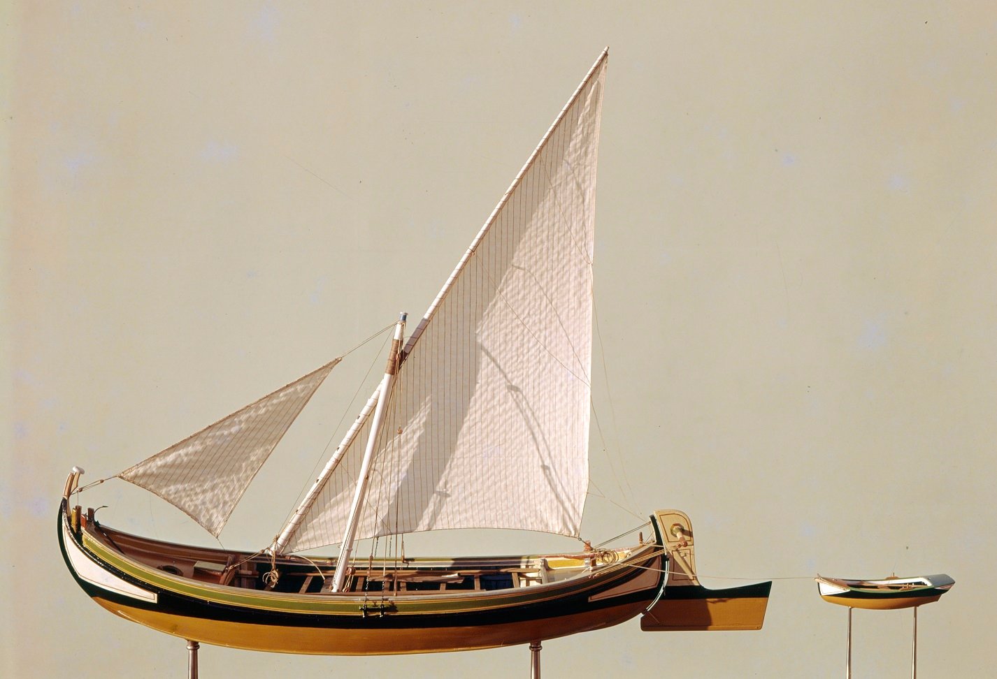
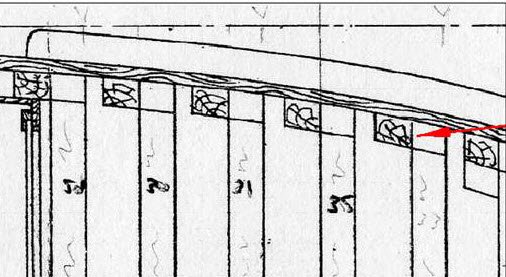
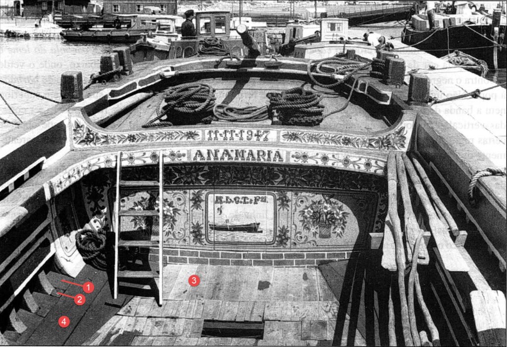
Note regarding the notch on the stern
The plans show an elliptical notch on the stern. After much speculation, this was determined to be an aide for keeping the oar in place while sculling the boat, as evidenced by the photograph on the right. Note the small boat in front of the larger vessel to the left.

Similar Vessels
Varino
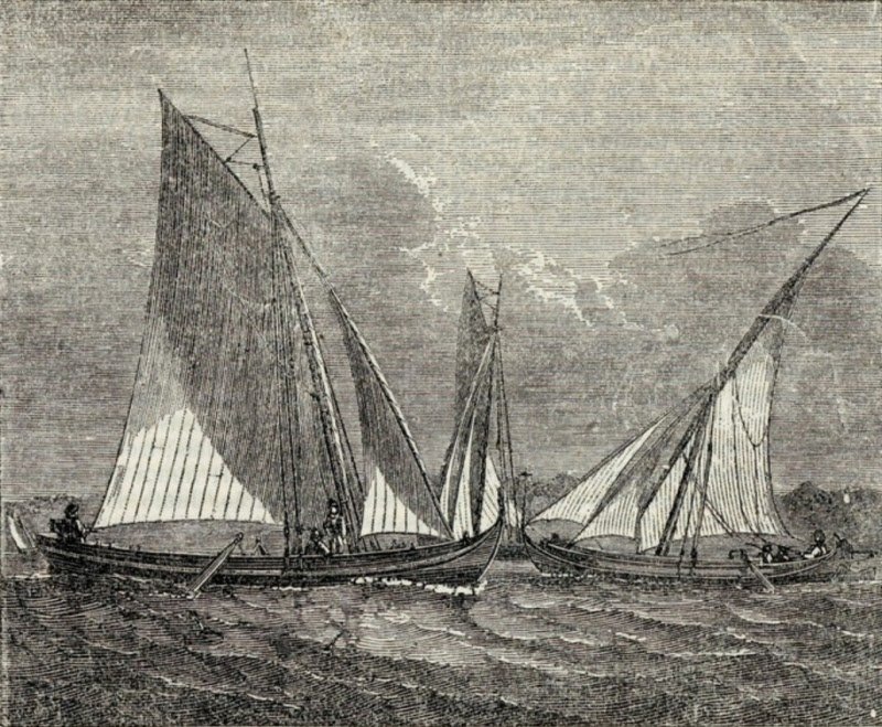
The varino is the transom-sterned version of the culé. This has been noted in various sources, but on this page the primary reference is the article by Kochiss. Early varinos were sometimes rigged with a lateen sail, but as time went on they were all fitted with gaff sails [recall reading this, but source required].
Elsewhere on this page:
- Etching or engraving of a varinho and a culé
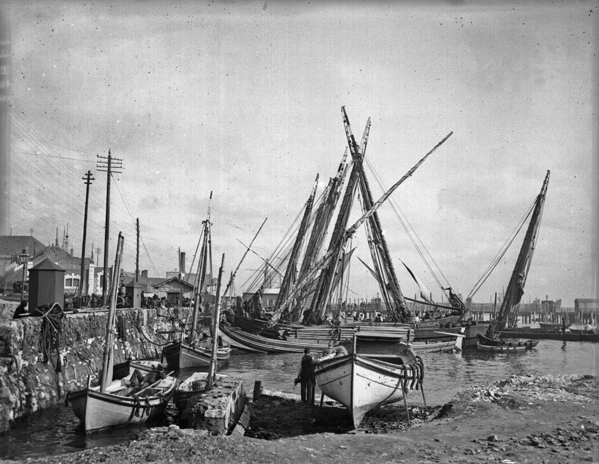
- Photo of a lateen-rigged varino being poled in a canal
- Photo of a lateen-rigged varino at a quay
Moleciero
The moliceiro is similar in many respects to the culé:
- no keel
- upswept stem and stern posts
- side frames and floors (but the floors of the moliceiro are inline whereas those of the culé are lapped)
- long, shallow rudder controlled by block and tackle led to a transverse pole (the “xarolo”) through the rudder head
Materials
The frames where made from cherry for the chata and from poplar for the culé. For both models, holly was used for the hull planking, upper deck planking, wales, and inwales. Floor decking for each vessel was constructed from fruit pear.
The cherry was from a tree felled by hurricane Isobel, which had been left in short pieces on the street for the city to collect and burn. Fortunately, the homeowner was a coworker of my wife’s, and when the topic came up at the office she let me know immediately. A fellow HRSMS member helped me collect it and I gave him what I hope was a generous share. The pear came from the parking lot of an antique dealer in the area of Toano, VA. I’d seen the tree standing on a previous visit, and when we returned I found it on the ground cut into fireplace lengths. I asked the owners what they planned to do with it, and they replied it was destined for their woodstove. I offered to trade them seasoned oak I had for our fireplace, and they agreed. I made two trips, taking all I could fit in the trunk of our Ford Taurus (this was the late ’90s). I’ve taken several holly trees from my wooded back yard, either where the woods were becoming too thick or I needed to clear space for a shed. I’ve also collected a lot of holly left on the roadside in my neighborhood for the city to pick up and turn into compost. The wood for this model came from one of those sources.
All the metal parts were formed from brass rod, tube and sheet, except for the shroud chains and forestay hanks. The rigging line is leftover from model kits. I bought a bag of the line at our almost-annual club auction. I’m not satisfied with the quality and for future models I plan to purchase better commercially made rope or lay up my own.
The paint is Ronan Japan Colors.
Chata
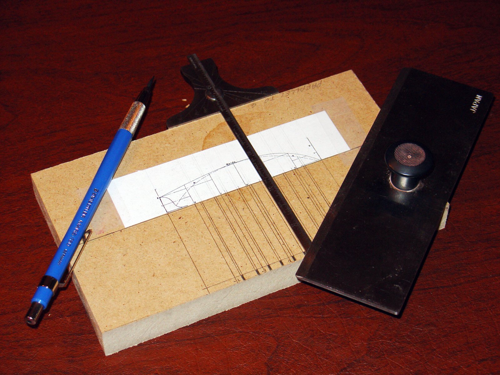
Building Board
A centerline was drawn parallel to one side of the building board so that the tee-square could be used to draw lines across the board at each frame location, using a copy of the plan as a guide. This depth gage makes an excellent miniature tee-square.
Frames
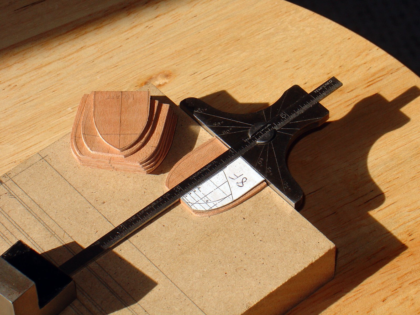
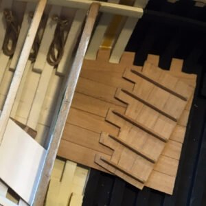
Roughing Out
The first step was to make templates for each individual frame. The templates represent one half of the frame, port and starboard. A centerline was drawn on blanks of 0.05″ (1.25mm) thick cherry wood. Again, using the depth gage as a miniature tee-square, the template shape was drawn in mirror image about the centerline to give the full shape. Given the small size of the drawings, I was not confident in the accuracy of the templates, so I cut well outside the line. The image below shows this process after the outside shape was cut away.
Fairing the Outside
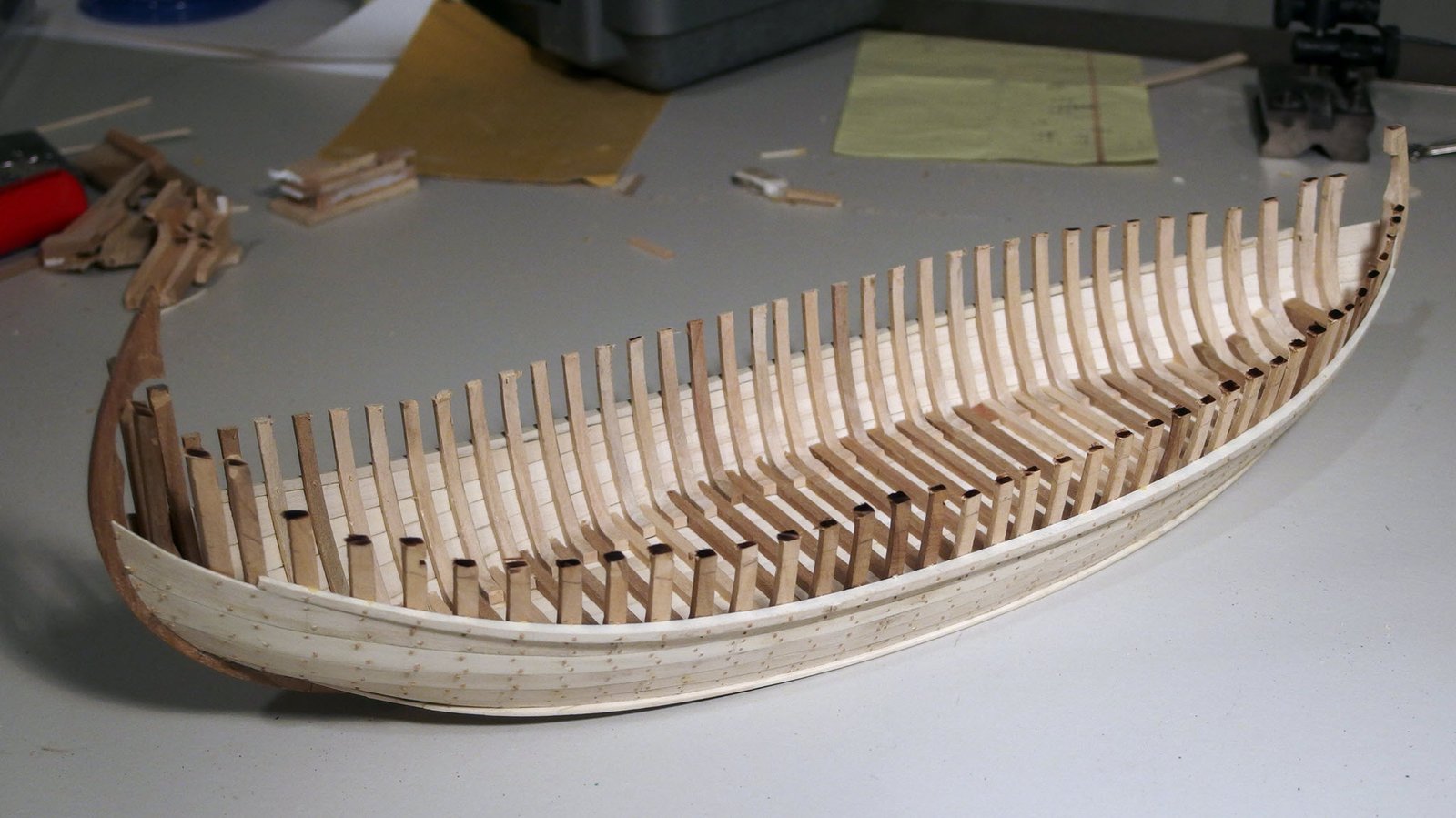
Because the boat is carvel planked, the frames must (or generally do) come first. But since there is no keel, something must provide temporary support to hold the frames in position. I suspect that on a real boat (or a model at a larger scale) the frames are secured to the ground and/or overhead beams by temporary bracing. This is not feasible for a model at this scale. Instead, I inserted solid spacers between the frames. These also provide much-needed support while shaping the delicate frame pieces, which are only 50 thousands of an inch thick.
The frames were only rough-cut in the first step. To arrive at the final shape they must be assembled together on the building board and faired. Not until the outside shape is determined can the inside shape be drawn and cut away. So it must be possible to remove the frames from the board, cut away the inside shape, and return them to the same position. To ensure the frames cannot move about, and to allow them to be removed, cut, and replaced in the exact same position, the frames were attached to the spacers using small pegs, sanded flush with the surface of the frame. Each frame and spacer combination is secured to the building board using small screws, the full assembly forming a many-layered sandwich. The stem and stern pieces were then added, as it was necessary to have them in place in order to properly fair the frames.
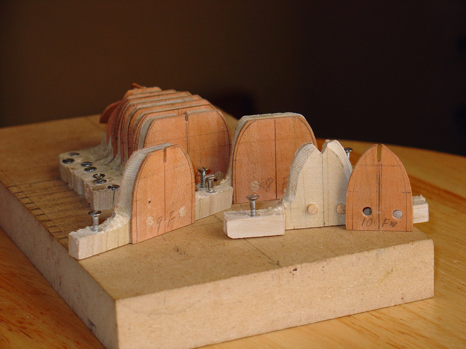
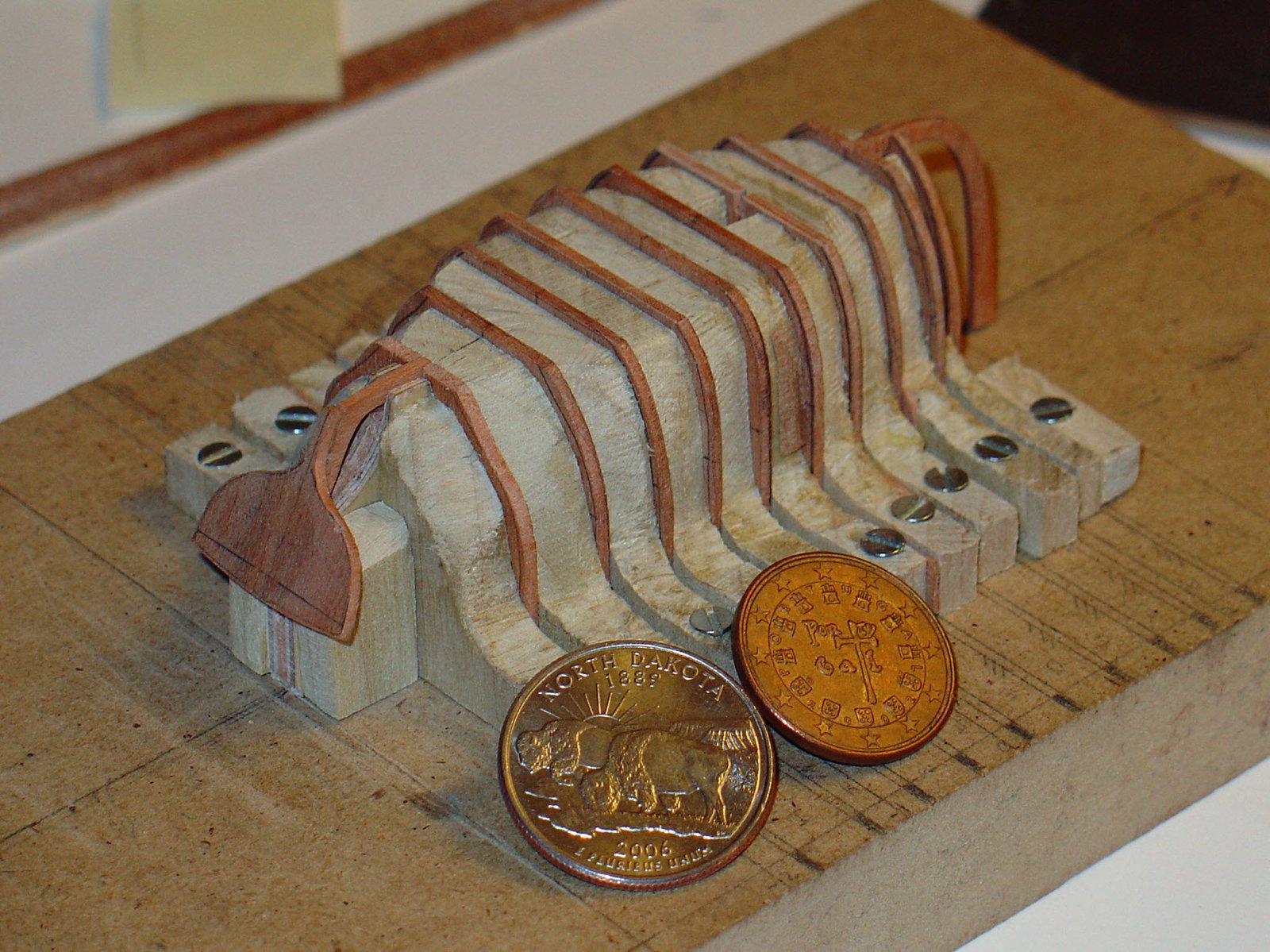
Frame Inner Shape and Floors
Once the outside shape was faired, the inside of each blank could be cut away to create two separate frames for the port and starboard sides, still temporarily attached at the base of the spacer. The two sides were then connected by a floor piece lapped to the frames. At this stage, a notch was cut out of each spacer to allow room for the floor. Note how the wooden pins allow the assembly to be returned to the original location of the solid blank.


Hull Planking
Here you can see the planking underway. The planks are 0.02″ (.5mm) holly.


Once the planking was complete, the port and starboard frames were cut away from the extra material connecting them at the base of the spacer.


Note the poor shape of the sheer plank along the starboard quarter. To fix it, a thin strip of wood was glued to the outside and faired into the hull. This results in the plank being excessive wide in middle of the repaired region, but this was fortunately hidden by the deck in a latter stage of construction.


Decking
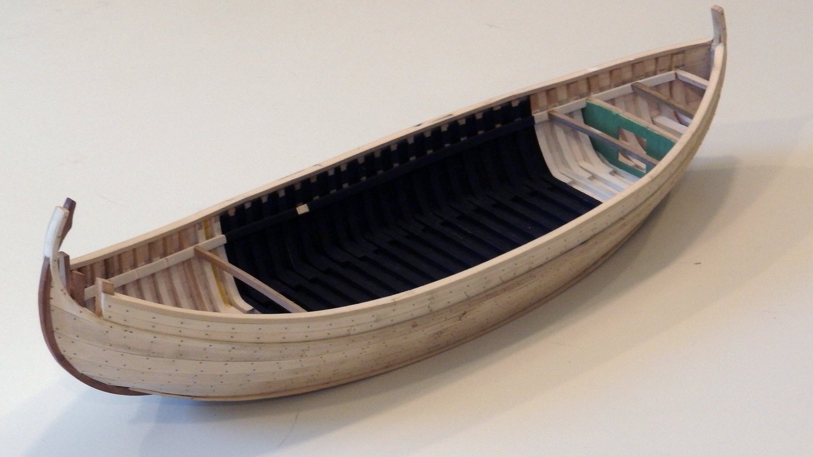
The inside was painted, with masking tape over areas where the decking, thwarts, and inwale needed to be glued. These object were then fitted.
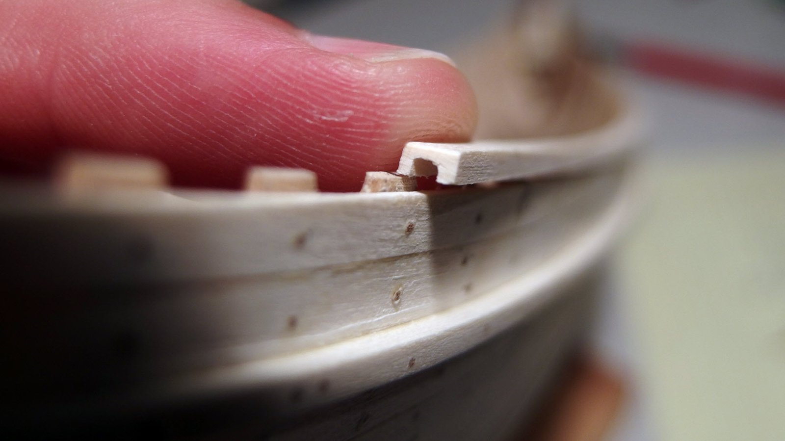
The margin planks for the floor decking were very difficult to fit, and the pieces very fragile. The little tab on the forward end of the port plank broke off. Unwilling to start over, I glued in back on, hoping the seam would be invisible. It was not 🙁
Note how the deck hides the ill effects of the repair mentioned in the previous section. All that is missing at this stage is the oars, thole pins, and paint.


Culé
Framing
The building board
There were two particular challenges to overcome with this boat:
- The heavy sheer plus the depth of the stem and stern pieces
- Absence of a keel
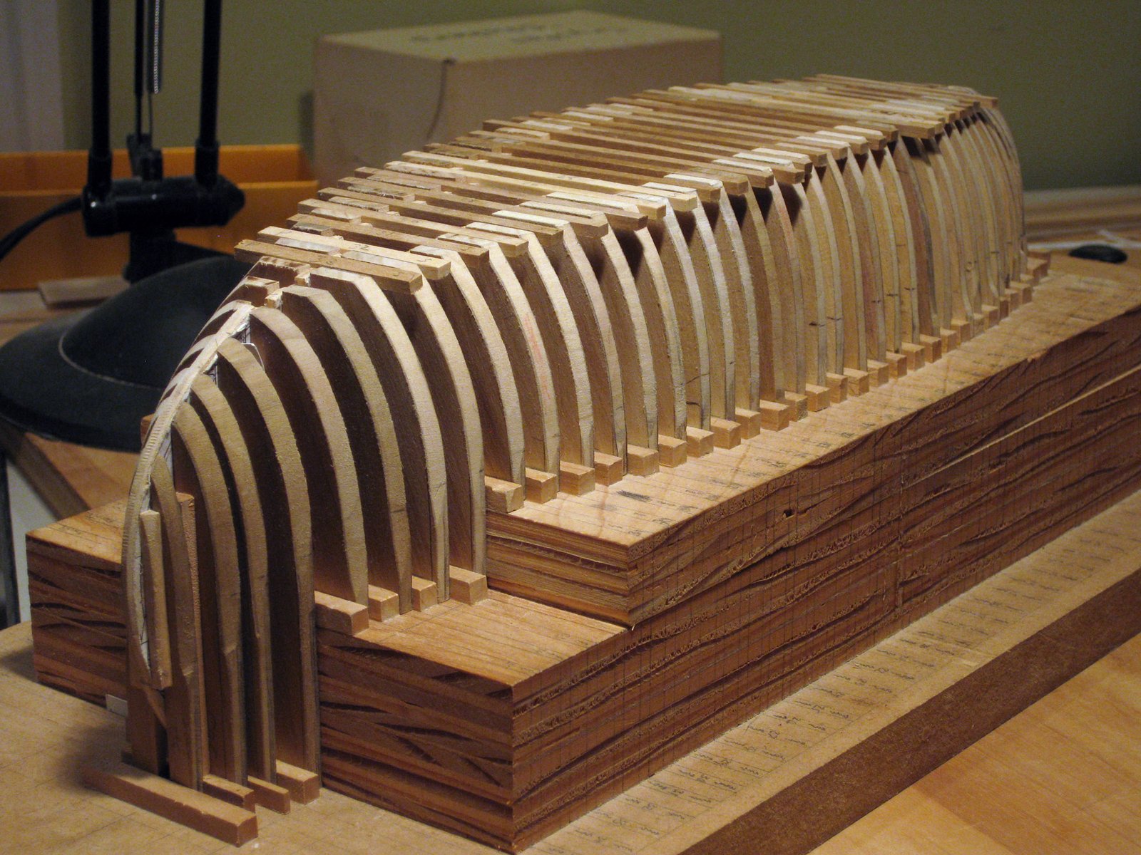
I did not think it would be easy to build it right-side up. Due to the high amount of sheer and the extended stem and stern pieces, building it upside down on a flat board would result in a lot of wasted material. To avoid this, I created a wedding-cake style building board. With the center section elevated, less material is required for the frame blanks – approximately 1-5/8″ in length instead of 2-1/2″. The stock can also be of a narrower width. I had 1″ thick poplar on hand, but a flat board would have required it to be 1-1/4″. As you can see in the sketch, I planned to keep the grain aligned with the long edge of the side frame as much as possible.
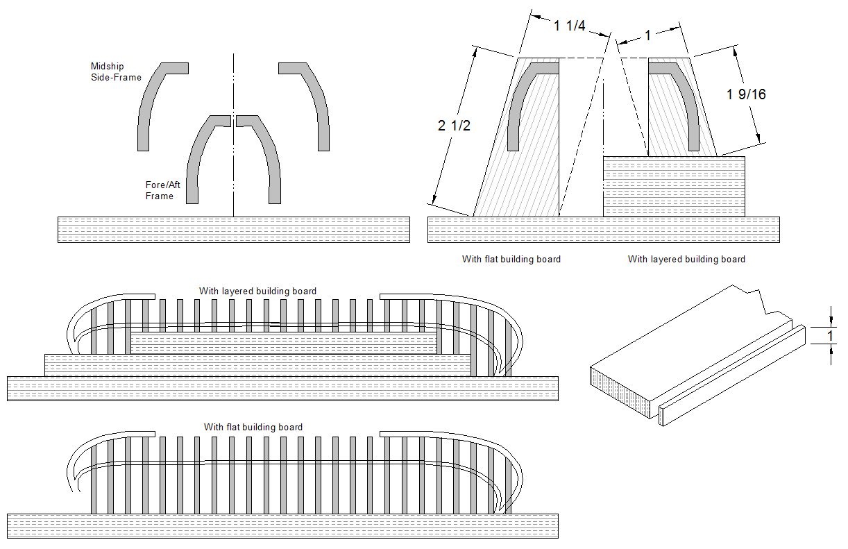
I first laid out the frame locations, centerline, and buttock lines on the bottom layer. I then glued two thicknesses of 3/4″ plywood together for the second layer, squared up their edges, and screwed the assembly to the bottom layer from underneath. The plan was that by not using glue, the upper boards could be removed and a cradle attached to the bottom board when the planking is done and the model turned right-side up. Thus all the frame marks could be used for reference. The frame marks were no longer necessary and I never did create such a cradle.
The marks on the base board were then transferred to this second layer. The second layer was removed from the bottom and a third glued to its upper surface. The assembly was then reattached to the bottom layer and the frame and centerline marks transferred to the top-most layer. A great deal of care was taken transferring the lines to make sure everything stayed square.
Because there is no keel, some temporary structure is needed to keep the frames in alignment during fairing and planking. Where the boat is wide enough, two parallel pieces of plywood were cut to the shape of the profile and notched to accept the floors. The outside edges of the plywood are aligned with a buttock line to form a “fence” related to a known position on the drawing. The spacing provides lateral stability to the floor pieces and minimizes the size of the wood required for the side frames. The inside edge of the frame templates are cut to these locations. A removable piece of plywood was added where the stem and stern piece would ultimately be placed. It was cut to the rabbet line to aide in fairing the frames.
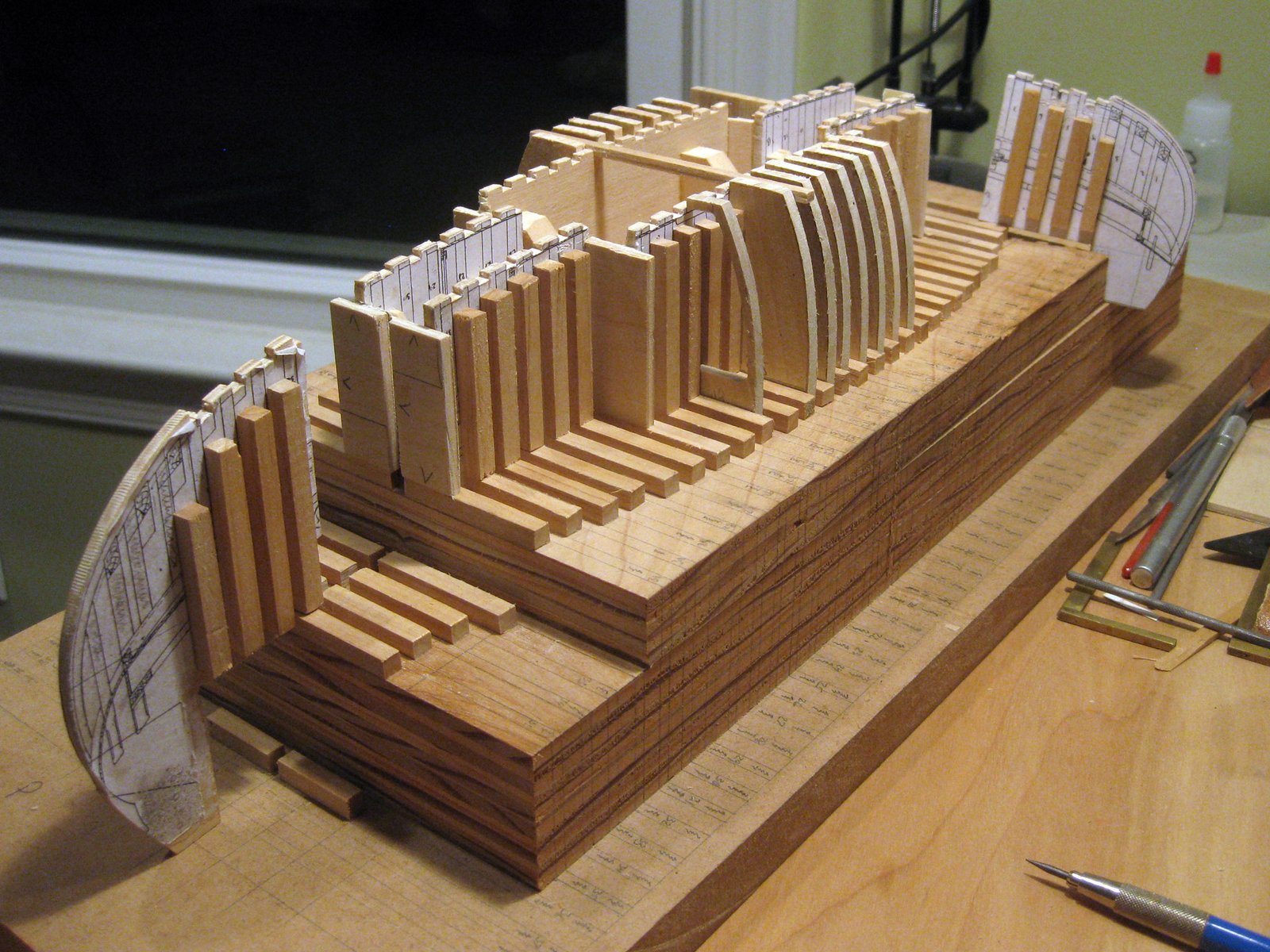
The foremost and aftermost spacers are not yet in place.
The photo also shows one frame cut to the inside shape, but this is from a previous attempt.
It was placed, along with one floor, to show the intent.
Along the length of the jig there are pieces of wood to fill in the space between frames. The frame were friction fit between the spacers. With humidity changes it was sometimes necessary to do a little sanding or add paper shims. Any frames that were unacceptable could be easily removed and replaced.
Each frame consists of port and starboard side-timbers and a floor timber that connects them. As with the chata, I was not confident in the frame templates I created, and so resolved to do final shaping on the building board, remove the side fames, cut away the inside shape, and then attach the floors.
Fairing
Many how-to books will suggest a block of wood used to fair a few frames at a time. I prefer to use a flexible fairing board covering as many frames as possible.
I make fairing boards from a strip of wood that is the same thickness as the planking, or slightly more (never less). I cut strips of sandpaper and adhere them to the strip of wood with double-sided tape. Others use rubber cement, but that’s a bit messier.
To get a grip without your fingers being in the way, the strip of wood can have small blocks of wood glued at either end on the side opposite the sandpaper. Don’t make them too long, as they stiffen that portion of the fairing board.
The floors also had to be faired. The floors amidships are rectangular, but as you go to either end they become trapezoidal. I measured the angles from the drawing and attempted to cut them on my Proxxon table saw, which has a tilting arbor. That did not go so well, so I created a jig to sand them to the correct angle. That process is outlined in detail in this Shop Note.
Rather than making a dozen or more jigs, I grouped frames that had nearly the same angle and cut them all the same. The final sanding on the outside would account for the differences without taking off too much material on any one frame, making it noticeably thinner than its neighbors. On the inside, I did not think matching angles (where a gradual change would be expected) would be noticeable either, and made no plans to fair the inner surfaces.
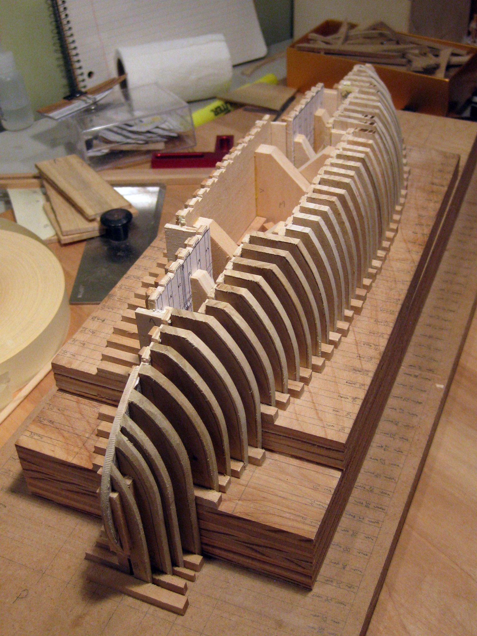
As for relative position, if a frame was too high, the notch in the jig was filed down. If it was too low, a paper shim was glued to the bottom of the notch. Sadly, I did not cut all of my side frame blanks longer than needed, and some of them ended up short. Since they were all to be painted and were already faired, I glued a thin strip of holy to the bottom of any frame blank that was too low, rather than starting over. I could have used poplar to match the frames, but the holly was already at hand and the frames were to be painted anyway. Due to the contrast in the wood, you can see see some of these ‘shims’ in the image below.
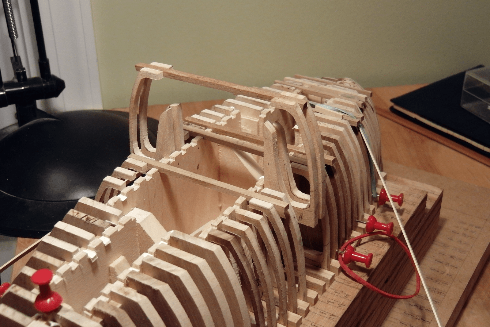
Side Frame Inner Shape
The inside of the frames are tapered, thinning from the bottom to the shearline. I shaped two notched pieces of wood, one notch being the depth near the bottom of the frame and the other equal to the depth at the shearline.
I then traced the shape of the forward and aft sides of each frame onto cardstock, making a notch at the location of the shearline. I laid each of these templates on the wood, shifted upward by the depth of the floor, and marked the top side of the frame where it overlaps the floor.
The next step was to slip the frames, broader side up, under the notches of the two pieces of wood mentioned earlier. These pieces were pinned to a piece of cardboard at the appropriate locations. The template was pushed up against the “nose” of each notch, with the bottom corner aligned with the mark for the top of the floor. Only the corner touches this mark because the template is rotated to lie against the notched pieces of wood. Then the inside edge is marked on the wood.
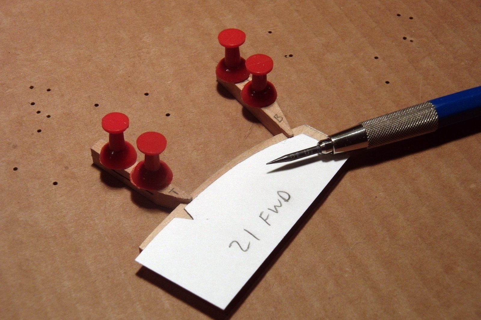
The procedure described above is repeated for the opposite side, but due to the bevel of the frames, the notched pieces of wood cannot be simply pinned to the cardboard. Instead they are set on their sides and aligned by eye with the outer edge of the frame. A mark is made at the top and bottom. The inner surface is drawn with the template aligned with these two marks, again with the bottom corner set at the mark for the top of the frame.
A jigsaw was used to cut to the lines marked on the narrower side and the bevel between the two sides of the frame was filed by hand.
No fairing between frames was necessary on the inside. With the process above, the inwales and shear clamps lied along the frames without any high or low spots.
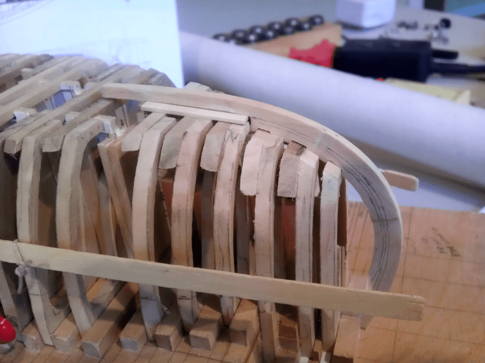
Frame Assembly
After cutting the inside shape of several frames and placing them on the jig, it was apparent that the frames had ‘sprung’, tilting inward or outward from where it was still attached to the base of the frame blank. Presumably, there was residual stress in the wood, and once cut to a narrow width at the bottom, it could alter shape.
To align them, it was important to only cut a few frames at a time, using the remainder to support a batten to which the cut frames could be aligned while attaching the floors. I glued the floor to one side frame, clamping it with cross-locking tweezers (useful in the tight space between frames). Then I could glue and clamp the opposite side, adjusting the length of the floor between the side frames such that each rested lightly on the batten. The floors were left long to be faired in with the frames after all were installed. Once dried, this assembly was rigid and could be used to support the alignment of further frames.
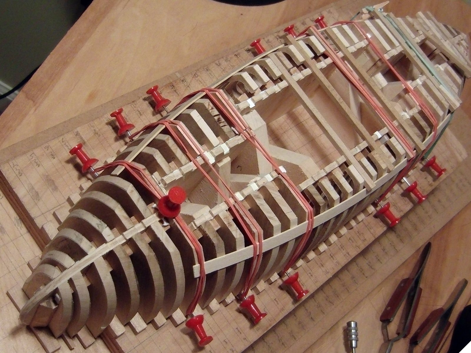
Warning! If you use rubber bands as shown in the photo above, pre-drill holes deeper than indicated by this image. To be secure, the push pins need to be driven further in than shown here. I drilled deeper holes after this image was taken, and after a push-pin came loose, the rubber band launching it in a near-miss to my eye. Safety first! Once enough frames were cut away, I stopped using the push pins and secured the battens with string, which you can see in a later image.


Planking
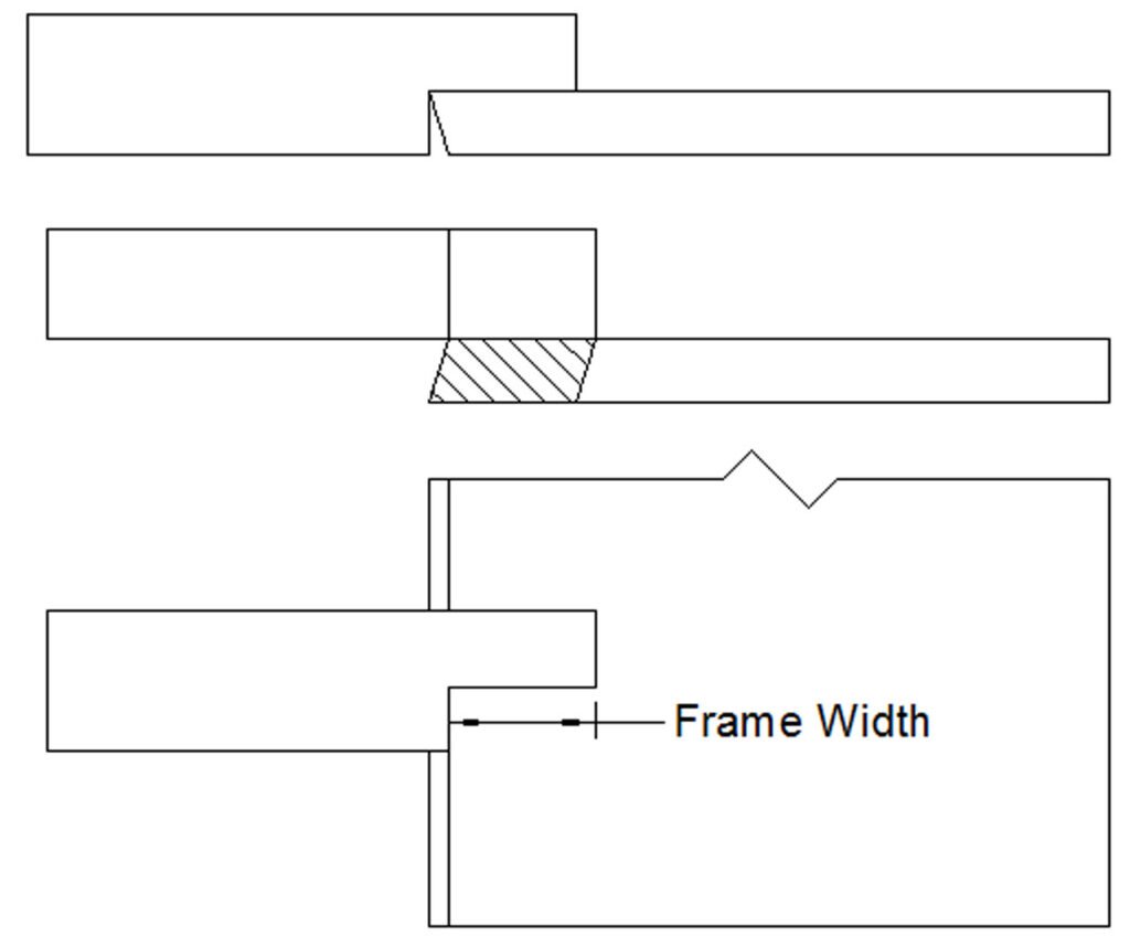
The wales were added first. The tapered thickness was achieved using a jig made for the purpose. The clamps shown in the image below were specially made to fit the narrow spaces between the frames and be adjustable for varying clamping depths. These clamps were a major effort to design, source, and construct. If I were to do it over again, I would use spring clamps with a bar super-glued to the surface. These are quick and easy to construct. The only downside is that the depth is not adjustable as in the special clamps. To ensure the sides of the spring clamp bear on the frame, it would be necessary to temporarily attach spacers to the inside of the clamp or bar.
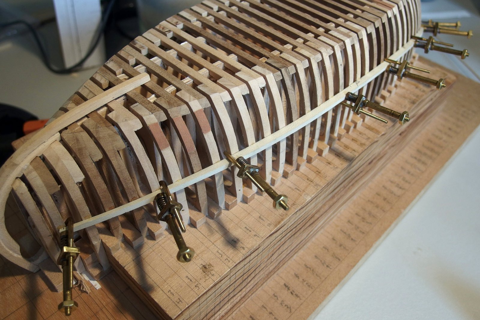
Two planks along the centerline on the bottom came next, so that the stem and stern pieces could be fully aligned and glued in place. These were followed by one plank on either side. With the wales and these four bottom planks installed, the frames were quite rigid. The two outboard bottom planks overlapped a seam on the center planks about midships, but did not extend to the ends. That was so the garboard strake could follow. With the garboard strakes installed, the remaining bottom planks could overlap the garboard strake, to be trimmed to a fair curve later.


Where the wale continues into the stem the stern, both the inside and outside had gaps that needed to be filled. I’m still not certain of the actual construction, but perhaps the rabbet should have gradually moved to the very outside of the stem/stern, which would have brought the trailing edge of the hull planks aft and flared out the top edge, meeting the wale as it bends inward. I could not use the Mariners’ Museums moliciero as an example, since all of the hull planks extend to the fore/aft extremes, completely overlapping the stem and stern pieces.


With the fitting of the cap rail, the hull planking is complete.


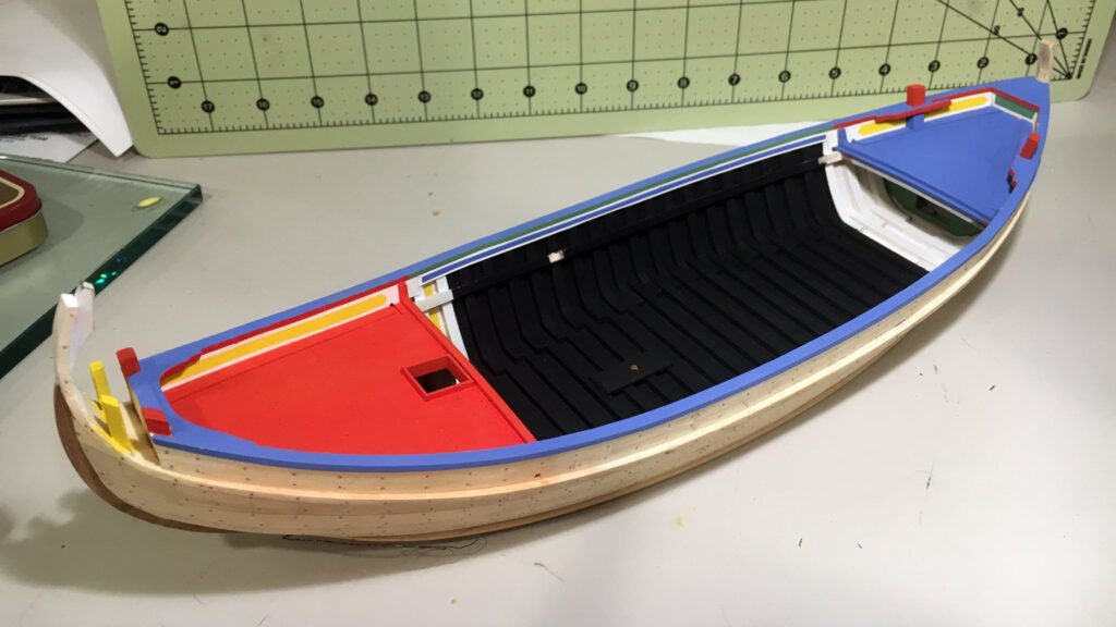
Hull Interior and Decking
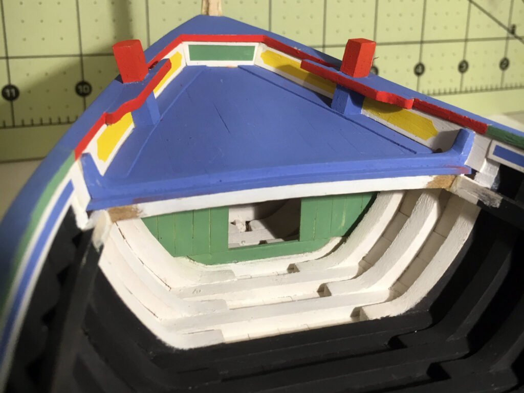
After finishing the hull planking and gunwale, the interior of the hull was painted, black in the hold area and white in the fore and aft compartments. Next the deck beams were fitted and the bulkheads installed. The aft bulkhead has an opening with no door, and the forward one has a sliding door.


A small LED light was installed in the forward cabin so that viewers can get a better impression of the framing. In the hold area the bottom is mostly covered by decking panels. The wire is led down the side of the hull behind a side frame, hidden from view. It exits the hull through the stem and down through one of the stanchions on which the model rests. A drawer at one end holds the battery and switch, which can be activated by a spring-loaded brass plunger.
I added a bench, box, and 3 rope coils to the forward compartment to add some small sense of realism. No doubt that it would be much more crowded in real life. Not knowing what should be expected, I erred on the side of sparseness rather than risk of placing objects inappropriate for the space. I have no idea what’s inside the box…. 😉


The plans clearly show the decking boards in the hold arranged in panels. I initially had the margin planks for the outboard panels include the spaces between the frames, as the plans did not indicate anything different.
Then I found this entry in Barcos do Tejo:
Inside the vessel, removable floor boards are fitted between the bilge stringers, in panels of varying sizes. […] Outside the bilge stringers, the spaces limited by the frames and the outer planking are filled with small rectangular finishing boards that are wedged into place, resting in part upon the outer end of each floor, to which they are nailed down. These are the tabiques grandes, the tabiques pequenos being smaller pieces of wood placed over the concavity of the side frames, between the tabiques grandes, to complete the smooth surface going out to the hull planking. The function of the tabiques is to close off the openings outside the bilge stringers, at floor level.
Barcos do Tejo, p. 170
The text above is the English translation of the original Portuguese found on page 64 which includes a corresponding photograph. I am instead including the photograph on page 86 that shows the tabiques much more clearly, though in this case the deck panels are replaced at least in some areas by individual boards, crudely cut and fitted – perhaps a hasty repair after some damage or decay.
Referring to the image above, you can see that as the fragata’s bilge stringers physically separate the deck panels from the tabiques, it is impossible for them to be integrated. The culé does not have the fragata’s rounded bilge, and thus lacks bilge stringers,. Thus, I still had the choice of whether to integrate them or have them as separate assemblies. I considered that removing and replacing the panels would be much more tedious for the boatmen if they had to be fitted between the frames. I therefore opted to make them separate, as in the fragata, though this is not indicated in the plans for the culé. I also omitted the tabiques pequenos as they are unnecessary in this case. Unlike the fragata’s bilge stringers, the deck panels of the culé can easily extend to the upright portion of the frame, leaving no gap to be filled.
The chata should probably have been treated similarly, but the decking was firmly glued in place long before I made this discovery. I decided it was not worth the risk to alter it.

Painting
Painting is easily the most tedious part of model making for me, so I have no idea why I chose to do a Portuguese boat. There was a lot of masking to do and mistakes to correct. Painting had already begun in the earlier steps, but it got trickier from here onward. The next few pictures show the progress.


The “Oh #&^@” Moment
At some point in the painting process I bumped the stem and broke it off. Fortunately the break was jagged and layers of wood overlapped one another. When put back in place the fibers meshed neatly and the break barely showed on the outer surface. A bit of glue and a clamp in each direction produced a strong bond. It turned out to be a non-event, but you wouldn’t know it from my initial reaction!


Outfitting
Soldered Parts
I’ve never soldered anything before, so this part of the model was a challenge – a challenge perhaps made easier with the gift of a resistance soldering system from my parents.
The boat hook is a piece of brass rod drilled using a lathe to accept the end of the shaft. It was then reversed in the lathe and a cone-shaped point formed using a file. I filed a notch on the side into which a bent piece of wire was laid and soldered. The shaft was worked down to the appropriate outer diameter using a draw plate. The end was then turned down in the lathe to fit into the head of the boat hook. This was later blackened (as well as other parts) using JAX Pewter Black, which is formulated to also blacken the solder. More on that later.


The mast hasp was the most work. I did not have any thick-walled tubing, so I drilled out a solid rod to form the hoop of the hasp. To account for the mast rake, a ring was cut off at an angle using a Proxxon chop saw, and this was then cut in half. To this were soldered some pieces of brass bar, a long one for the clasp and a short one, at the end of which was soldered a piece of tubing to form the center knuckle of the hinge. Two strips of brass were bent into a u-shape to form the leaves of the clasp and hinge on the thwart. To one was soldered a bit of brass, rounded and dilled for the clasp pin. To the other were soldered two thicker pieces of brass, also rounded and drilled, to form the outer knuckles of the hinge. Among a pile of model parts bought at an auction, I was fortunate enough to find a scale bolt with a rounded head and of the perfect size to use as the pin for the hinge.
One of my favorite parts of the model easily goes unnoticed. Perhaps that is why it is one of my favorites. It is one of the simplest in appearance, but was not easy to make. To make the proportions correct I drilled out a tube to make the wall thickness even thinner. It could not be parted off without crushing it, so I inserted a rod as a backer. Once cut off, the tube did not want to come free of the rod. After a few attempts I got one that was satisfactory. To one end I soldered a disk of brass and on the outside a bit of wire to form the handle. It was hard to solder the wire without melting it. The end effect looks more ragged than intended, but it makes a convincing beat-up tin mug.
The top of the stove is from a solid piece of brass. I drilled a hole for the opening and then shaped the flare by hand with a file as it turned in the lathe. Next I parted it off where the grate should be, and parted off a second thin disk to form the bottom of the stove. I soldered on a few bits of wire to the bottom of the top piece and then soldered the top and bottom to the body of the stove, which was a piece of brass tubing. Lastly the handles were soldered on and an opening cut for the fire box.


The bilge pump body is a piece of rod with holes drilled at either end. A small hole is drilled to accept the pump handle and at the other end a larger hole is drilled to make it appear the entire length is hollow. That end is also turned down to match the drawing. The discharge is a bit of tube shaped to fit the pump body and soldered.

A number of eye bolts were required, either on the deck of on mast and spar hoops. Those fitted to the deck I needed a wide flange for the base. I drilled a hole for the shank and parted off the disk. Then I made a loop out of wire and soldered them together. I’ve included a lot of images for such a simple assembly, but as it is new to me I opted to show the entire process through blackening and top coating. The top coat of clear acrylic was intended to protect the blackening, which flaked off easily. I used a product made by Jax and varied the concentration and exposure time per the instructions and online advice. My best results still did not hold well.


Buckets and Mop
The shape of the buckets, as with most, is a truncated cone. I created a template for the unfolded shape using Solid Edge 2D. Drafting programs can be a valuable modeling tool, so I did an introductory demonstration of Solid Edge 2D for our club using this as an example. The recording is available on YouTube.
The template was taped to a piece of wood with the staves aligned with the grain. The species of wood is holly, which bends very well. After cutting away the outer shape I scribed sharp, v-shaped grooves so that the wood could bend in on itself. I soaked the wood in water and was disappointed to see that due the grooves I had cut, the swelling of the wood caused it to curl opposite the intended direction. I was able to force it back with only one break, creating two seams instead of one. With the grooves cut through as far as I dared, it could have been worse.
To hold the proper shape while bending, I turned a piece of brass rod tapered to the proper slope. The wet wood was wrapped around this and a washer slipped over top of the wood to hold it in place. I applied some heat with a hair dryer to help set the shape of the wood. Once dried, the washer was removed, the two seams glued, and the washer replaced to clamp it while the glue set. The brass plug had been waxed to prevent the wood from sticking.
The bucket was then painted and strips of colored craft paper where cut to form the bands. The same paper template was used to ensure the bands had the arc shape that would result in a circle after being wrapped around the cone.
The mop was formed by cutting slits in multiple cloth disks, which were then “skewered” over the end of the handle.


Barrels
To make the barrels I turned a dowel using my lathe. It was shaped by hand with a file and a carboard template to periodically check the shape. I used a hobby knife to score lines along the length in order to simulate staves. To get them evenly spaced, I used a drafting program to print out an index that I could tape to the circumference of the collet holder. I had a magnet from an old hard drive lying around. Attached to the gear housing, two faces of this magnet served as a platform for a square which in turn served as the pointer for the index on the collet holder. To mark the lines I inserted a lead holder (drafting pencil) into a boring bar holder for the quick-change tool post. Rather than attempt to draw the lines along the curved surface, I simply ran the pencil in at multiple points along the length and then laid a batten along the points, along which a line was drawn. As with the buckets discussed above, the barrel hoops were fashioned from colored construction paper, the proper shape being obtained using a template for a truncated cone. The barrel is not a cone, but the shape of two adjacent hoops can be approximated as strips at the top and bottom of a truncated cone.


Coming soon…
This Page is a Work-in-Progress. Please check back.


