Submitted by John Cheevers
Categories: [Hull Construction] [Solid]
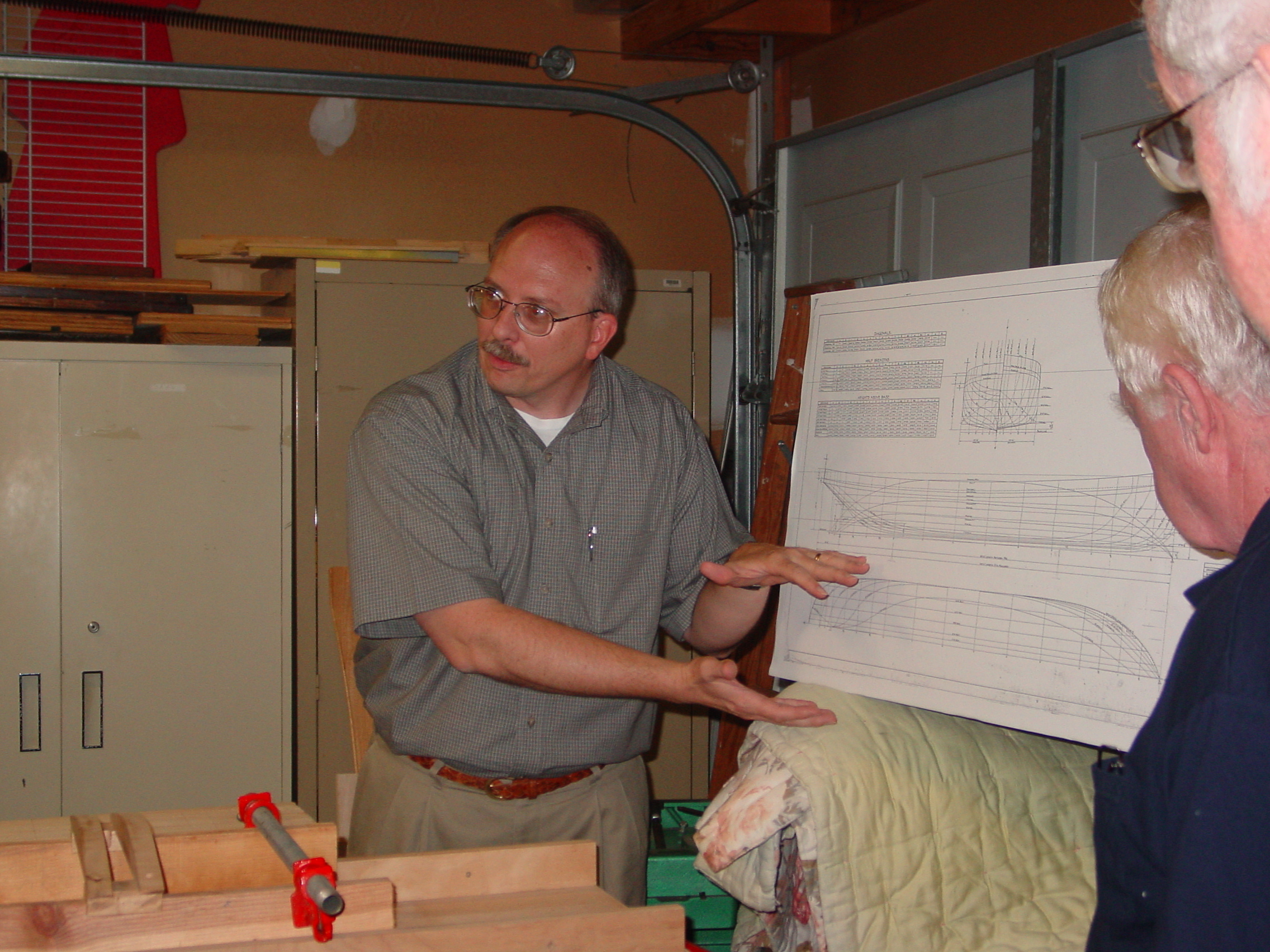
John Cheevers is a retired shipbuilder. His career at Newport News Shipbuilding spanned 46 years and fairing hulls is now second nature to him. He has made several presentations over the years describing his methods for building solid ship model hulls. This Shop Note covers three of his presentations, which are given in reverse chronological order.
June 2023
This is an extension of his presentation from May 2023, this time focusing on chined hulls. A PDF version of the Power Point file John used during his presentation is provided along with the recording of the presentation.

May 2023
Unfortunately, the presentation was not recorded. We hope you will find this PDF version of the Power Point file John used during his presentation helpful.
September 2003
Introduction
These instructions will produce a solid, flush-decked hand carved hull with a machined upper deck including shear and camber
Plans
Study the ship you are building. Try and visualize the hull shape. Determine what the hull must look like to suit the way you will build the model. Got it? Good! Now establish, on the lines plan, the hull block's baseline if it is different than the design baseline. Note the waterlines, do they correspond with the thickness of your lifts or will you have to draw more? Look for design elements that will complicate the carving such as tumblehome, flair, and drag. Establish where the mounting pedestals will go. Locate lightening holes in the inner lifts on the plan. Make as many copies of the plan as you need to make templates (each template should correspond with a station or frame.)
Material
Select your wood. I use bass, but you can use others such as yellow poplar or sugar (pattern makers) pine. I like bass; it is a medium hard wood that is easy to carve, has a uniform texture, and possesses great dimensional stability. Now, to determine the amount of lumber you need, measure the hull's overall length, width, and depth in full size inches. Divide the depth by the thickness of stock to determine the number of lifts. Multiply the number of lifts by the overall length (add one to two inches to the length of each lift for scrap) to determine the number of inches of lumber to buy. Make sure the width of the boards exceed the width of the hull.
Templates
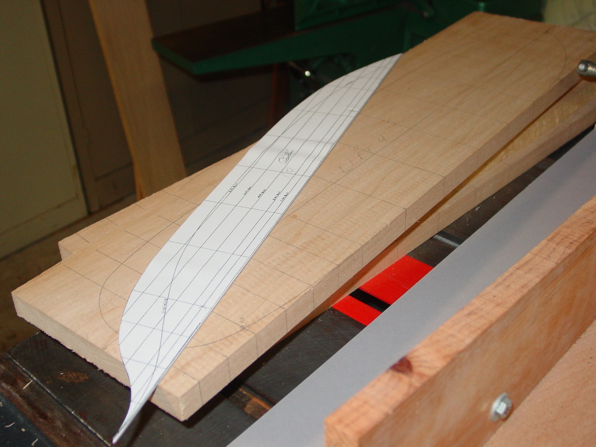
Those copies of the lines plan you made earlier become the templates. I make an accurate template for each section in the body plan, the stem and stern profiles from the sheer plan, and the bow and stern shape at each waterline from the half-breadth plan. I draw a rectangle about two inches larger on each side than a circumscribed rectangle around the body plan. I cut out these rectangles and split them down the centerline to produce forward and aft station shapes. I mount each one on matte board (make the matte board sections roughly twice as large as each drawing for stiffness) using a spray mount adhesive. On each body template, you need to draw the main or upper deck camber curve. Using an X-acto knife, I cut out each station shape by repeatedly tracing the frame and deck curve. Four or five passes with the knife should do it. These templates should hold their shape as you test fit them to the hull when applying moderate pressure. If they deflect, you need to remake them. Next, I make roughing out templates for each lift's waterline (see photo) and a profile template that can double as the tic strip (story pole) to establish frame locations. You may cut out the lightening hole in each inner lift at this time.
Layout
Before the pencil hits the wood, I join one edge of each board. This edge becomes the reference plane for layout and dimensioning of the corresponding waterline plane, drill hole locations, and lightening holes in interior lifts. The first thing you do is mark the FP, AP, and stations on each lift using the tic strip. Then with a combination square, square lines through these points on the top, bottom and joined edge of the lifts. Next reset the combination square to mark a consistent centerline on each lift. Mark this halfwidth at each end and join the marks using a straight edge. You will renew these reference lines as they are removed during sawing and carving.
Begin by drilling clearance holes at the pedestal locations for the mounting hardware; include a counter bored recess to accept a blind nut in the top of the first or second lift. Drill larger radius holes (3/4" forstner) in the corners of all lightening holes and finish cutting the lightening holes with a saber saw. Finally, cut the waterline shape from each lift standing clear of the line by 1/16" or better.
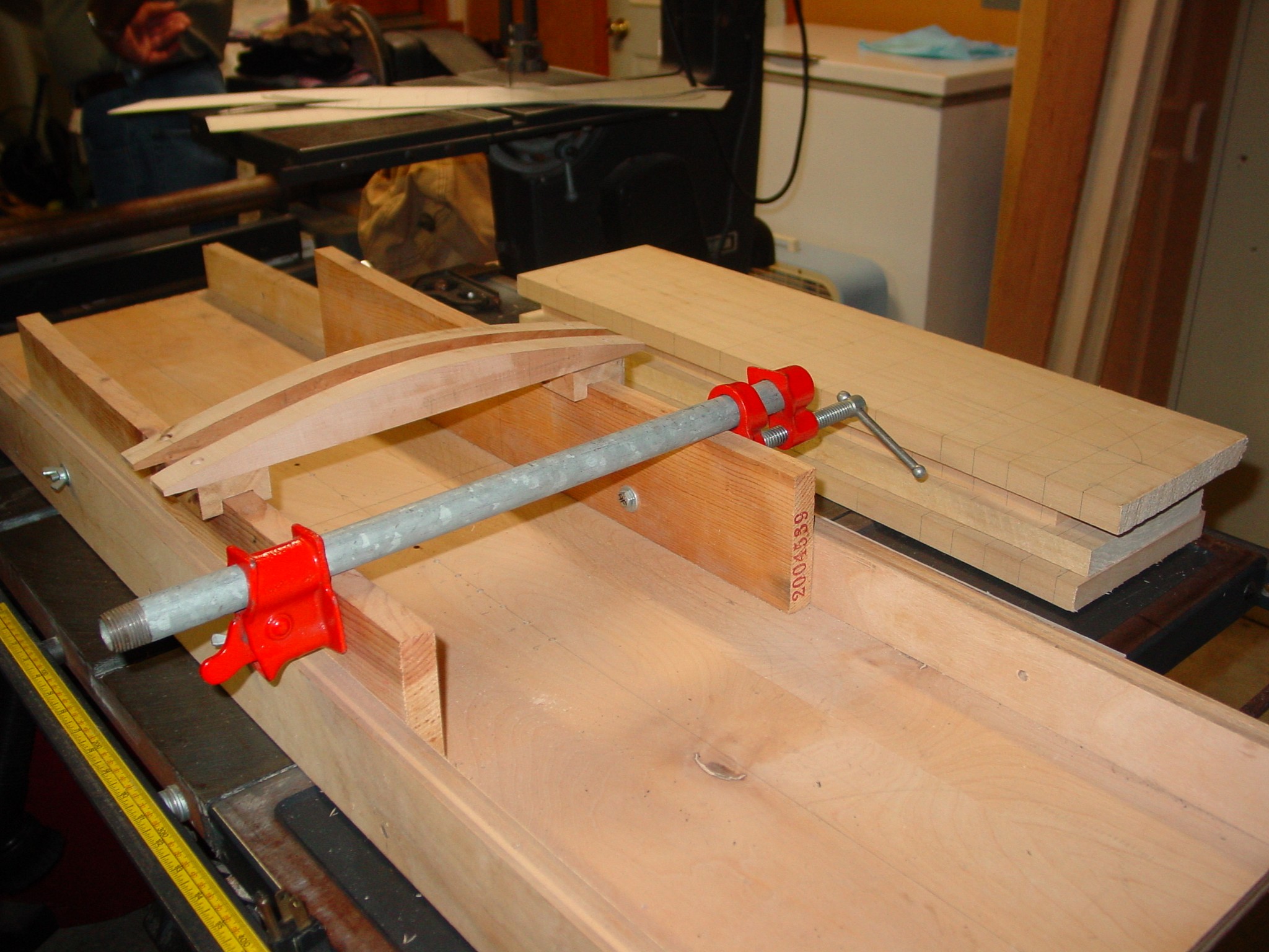
Gluing
Apply glue to the mating surfaces of each set of lifts. I glue them together two at a time, and then glue those sets together two at a time until the hull block is assembled. I don't use any reinforcing screws, nails, or alignment dowels. I loosely clamp the lifts together repositioning them as necessary to keep the reference lines aligned. When I am satisfied with their position and the tack of the glue precludes further slipping of the lifts, I add larger clamps and more pressure until I have an even squeeze-out of glue around the joint. Set the hull aside for a day or two to allow the glue to cure.
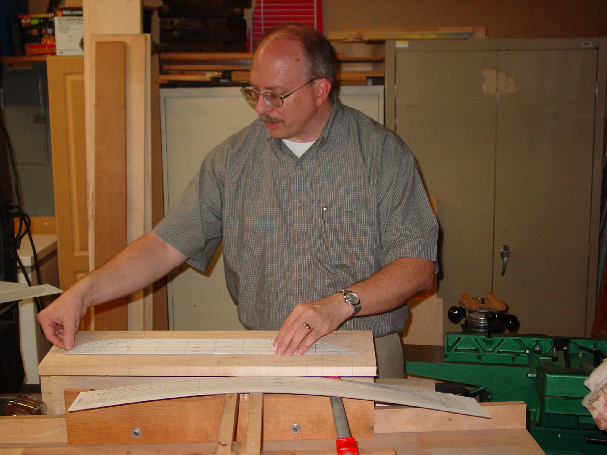
Cut sheer and camber
I use a home-built tool to cut the sheer and camber into the hull block. This can also be done using planes, chisels, and templates.
Carving
Using the plan view templates draw the bow and stern top deck edge shape on the hull block. Establish half-widths at the remaining stations and connect these points to the bow and stern deck edge shape lines with a flexible batten. Use the miniature plane to shape the deck edge to this layout line.
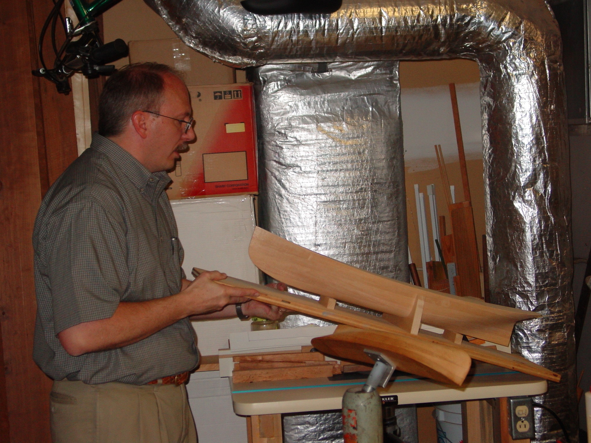
Vise
I mount the hull block to my carving vise immediately after cutting the deck edge to shape. I have a Power arm but you can make an adequate holding and positioning device from wood (See NRG publication Shop Notes for ideas.)
Carving
At the keel, layoff the drag and cut it into the hull with the jack plane, use the straightedge to control the cutting depth; afterward reestablish the centerline. Draw half sidings adjacent to the centerline. If you wish, you may use the jack plane to rough cut deadrise at this time. Next, I carefully cut the profile shape of the bow and stern at centerline from the hull block using the stem and stern profile templates. Then, I take a large sweep and quickly remove much of the excess wood on each lift. The rough-cut waterlines provide enough reference to guide you. Next, I cut each frame's shape. I carefully remove material at each station until the template fits with no large gaps and the template does not distort. Start amid ship and work toward each end. Finally, I remove the excess wood between each frame. When you are through, sand the hull, step back and admire your work. If you are careful, the hull should only require minimal sanding which greatly increases its fidelity to scale.
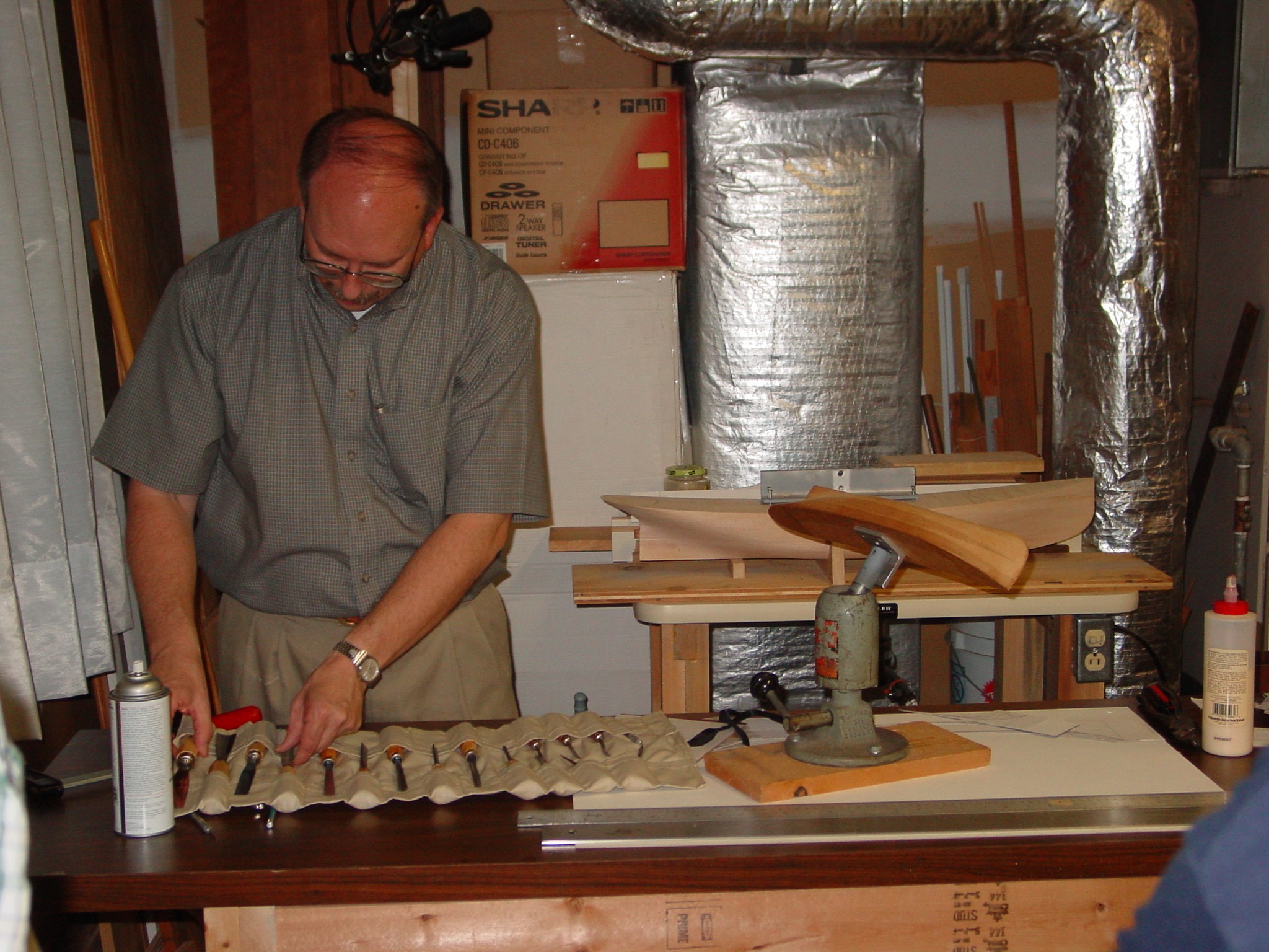
Tools
- Straight edge
- X-acto knife
- Mechanical pencil (to draw consistent width lines)
- Machinist combination square
- Ruler or scale
- Spray mount adhesive
- Jointer or jointing plane
- Jack plane
- Miniature plane
- Drill press and bits
- Power arm or other carving vice
- Yellow glue
- Chisels
- Although I have many chisels, I find that the straight, the #4 and the #3 are the only ones I use.
- Clamps