Submitted by
Categories: [Wood, Milling]
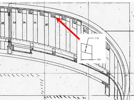
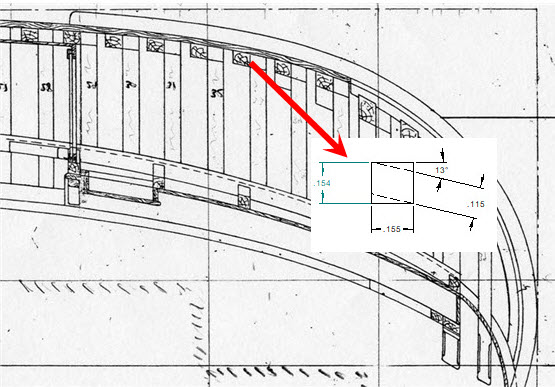
My model has straight floors that join port and starboard ribs. Those near midship have a more or less rectangular shape, but as you go forward or aft they become trapezoidal.
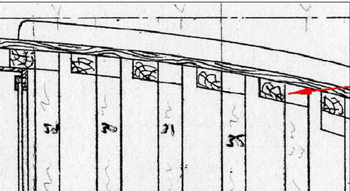
The stem piece (no keel) and bottom planking are at the top, the bow to the right.
The vertical, numbered timbers are the side frames.
One of the floors is pointed to by the red arrow.
I first tried cutting them using a Proxxon FKS/E table saw with the blade set to the proper angle. Even with an adjustable fence, consistently getting a precise width was difficult, and I had trouble getting very uniform thickness. This was at least partially due to a small gap between the fence and the table, allowing the tapered edge of the stock to slip under the fence to a varying degree. The supporting face of this fence is also not very long, making it more difficult to feed the stock in straight than it is with a normal fence.
In addition, my only blade at the time was course enough to leave easily visible marks, and significant sanding would be necessary.
Since I'd be relying on my thickness sander in the end, I decided to skip cutting the angle on the table saw. To get the correct shape, I created a series of fixed-angle jigs to be used with my thickness sander. This allowed me to work directly from square stock, and "sneak up on" precise dimensions. They should prove useful for other tasks requiring a bevel on a strip of wood. I've saved them for future use.
The downside is the need for a separate jig for each required angle. I contemplated a variable-angle jig, but did not come up with a design that was as stable or low-profile as the fixed-angle jigs. Depth between the sander drum and table is limited.
Two Options
These numbered options are referenced in the following sections
- Clamping surface to one side
This is the jig as I built it. While writing up the documentation, alternatives came to mind that have fewer steps, use less material, and do not require a full-size table saw. - Clamping surface at the end
- Flat section routed at each end of the jig
or - Glue the jig to a thin sheet of plywood
- Flat section routed at each end of the jig
Materials and Tools
- 3/4" MDF (dimensionally stable and no grain direction to be concerned with)
- Table saw or radial arm saw
- A full size saw is required for option 1
- A hobby-sized saw will be sufficient for options 2.1 and 2.2
- Table-mounted router with a split fence
- Straight bit
- Slotting bit (only for options 1 and 2.1)
Construction
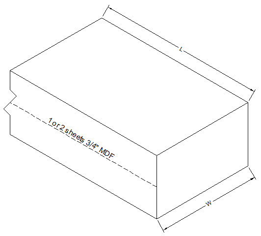
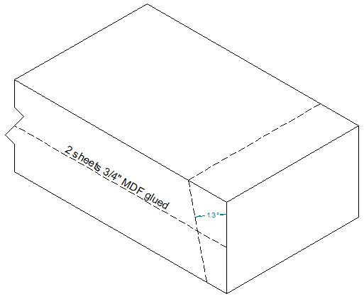
- Glue two sheets of MDF together (option 1 only)
- Cut the MDF to size
Make dimension 'W' the length of your thickness sander table (1" less for option 2.2)
Make dimension 'L' long enough to cut strips for each desired jig
- Cut a strip from your stock with the blade set at a desired angle. The thinner side should be about 1/2" (less if the capacity of your thickness sander demands it). Square-off the remaining stock and repeat at each desired angle to create more jigs.
- Route a grove to hold the work piece
- Align the two sides of the fence
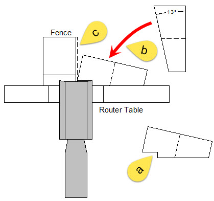
- Set the bit and fence to make a groove wide enough to hold your stock, and deep enough to keep it stable as it is fed into the thickness sander (a). The groove keeps the thickness sander from pushing the stock down the slope of the jig. The depth of the groove helps prevent it from rotating. The deeper the grove, the more stable the work will be. If you make it too deep, while in use, you will start sanding the jig before you reach sufficient depth to finish the work piece. However, this is not a problem.
- Lay the angled surface of a jig down on your router table with the thicker edge against the fence (b).
- Turn on the router and push the jig 1/3 to 1/2 way through the router. You will notice a gap forming on the opposite side. Turn off the router and pull the jig back out.
- Push the jig back in and adjust the out-feed side of the fence to engage the work piece (dashed line pointed to by note 'c' in the illustration). The piece will now be supported on the out-feed side, preventing it from rotating as you feed the last few inches through the router bit.
- Pull the work piece back out, turn the router back on, and feed the work completely through the router.
- Turn the router off.
- Repeat these steps for each jig
- Create a clamping surface
I think it is easier to have the jig fixed in place and move only the work piece through the sander.- Option 1
Flip each jig onto the opposite side, with the narrower edge against the fence. Using a slotting bit, create a flat surface on the top face - Option 2.1
Using a slotting bit and a right-angle jig or coping sled (preferred), create a flat surface at each end - Option 2.2
Glue the jig to a thin piece of plywood or hardboard that is the width of your jig and the length of your sanding table, centering the jig along the length of the plywood/hardboard
- Option 1
Use
The instructions below are for creating the parallelogram I required. Clearly, the same jig could be used to create a bevel on just one side, or any combination of angles you require.
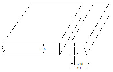
- Determine starting size based on desired final dimensions. In this example, the distances between the two sets of parallel faces are 0.155" and 0.115". The corresponding square stock is 0.155 x 0.154. Mill your stock to the wider final dimension.
- Saw away strips from the stock, equal to the smaller dimension plus some margin, which will allow for error and removing saw marks. In this example, I cut away ~0.2" instead of aiming for exactly 0.154".
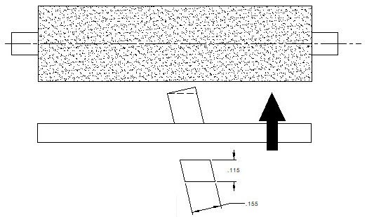
- Sand the first surface
- Clamp the jig the sander table
- Put the stock into the angled groove
- Sand a little bit at a time (raising the table after each pass), until the desired bevel is achieved.

- Remove the angle jig. Rotate so sanded surface is on the table. Sand until narrower dimension is obtained.
- Rotate to model orientation and admire your precision 🙂