Member since 09-Aug-1997

Build Type: Scratch
Country: Denmark
Era: 1815-1914
Length Range: 020-40 feet (6-12m)
Model Material: Wood
Model Type: Static
Propulsion Type: Impeller→ Sail
Scale: 1:24 (1/2″ = 1′)
Subject Type: Vessel→ Working→ Fishing→ Trawl / Dredge
De 13 Søskende (The 13 Siblings)
The model is in its early stages. Once completed, I will add a series of final images. Until then, I am including a limited set to show the latest progress. You can see more construction images in the tab below.


De 13 Søskende1 (The 13 Siblings) was an åledrivkvase1 (eel sailing drifter), a side-trawling fishing boat specialized for catching eels in the waters surrounded by the Danish Islands of Zealand, Falster, and Lolland.
Plans
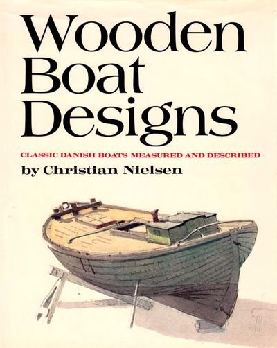
While living in Odense, Denmark for 10 months, I was introduced to the book Wooden Boat Designs2, which contains plans and descriptions of 41 traditional Danish boat types. At first, I had a photocopy of a photocopy of the original Danish edition. Wanting to go legitimate, I bought a hard copy of the same. I selected this vessel to model, but did not begin immediately, as other projects were ongoing. I then found the book translated to English and bought it. Still the model had not been started. When it became available some years later, I purchased a CD contain high-resolution scans of all the drawings, and still the naissance of the model was in the distant future. By the time I did begin the model, all of the drawings could be downloaded for free from the Maritime Museum of Denmark! I’m glad to have one copy of the book in addition to the scans, but I wasted money on the the original book and the CD. These links are to the three sheets for De 13 Søskende:
All of the drawings in Wooden Boat Designs were created by Christian Nielsen. Realizing how traditional local craft were disappearing due to the introduction of the motor and the specialized vessels that followed, the Maritime Museum of Denmark wished to obtain a record of the vanishing types. For fifteen years Nielsen visited different parts of Denmark during the summer months, traveling by train and bicycle. In the winter months, or when not busy in his small boatyard on the island of Fejø, he worked up the material he had gathered during the summer. The effort was all financed privately. He also managed to build 15 models between 1939 and 1953, including one of De 13 Søskende.
Mr. Nielsen was the grandson and namesake of the man that built De 13 Søskende. It is coincidence that, of the 40+ drawings within this book, I chose to model the one to which the author had a familial connection. I chose it for its aethetics, the somewhat unusal aft spar, and the very unusual purpose for which it was built (eel fishing).
Other Models
The drawings that Christian Nielsen (the younger) produced were not his first association with the museum. After finishing his apprenticeship, he took a job at Helsingør shipyard and continued his studies through a private tutor. He was introduced to the Maritime Museum of Denmark through this tutor, and the initial interest was for his skill as a model builder. The museum’s first request was for a model of De 13 Søskende. Here are three pictures of the model from the museum. The two black and white images are also available on their website.


Model of De 13 Søskende, built by Christian Nielsen, Fejø.
Model in the custody of the Maritime Museum of Denmark.
Photos: Maritime Museum of Denmark
One interesting piece of information not found elsewhere is the vessels registration number, which is seen on the sail and the bow.
Historic Photographs
The image below is of De 13 Søskende later in life, after the fitting of an engine and a change in owners and hull color. This information comes (via fejoe.info) from Mie Lobedanz, great-granddaughter of the original owner . It is not a direct translation of the original source. Some details repeated elsewhere are omitted and the order rearranged to suit.
De 13 Søskende was owned by my great-grandfather Jens Peter Jørgensen, Askø. He had thirteen children with great-grandmother Sofia, hence the name. When he went out
fishing, he had a sack with all the children’s worn-out clogs, which he sat and repaired when there was a lull in the fishing.After a few years, the drifter got an engine. After changing owners a few times, in 1937 it belonged to fisherman Poul Hansen of Fejø.


Built by Christian Nielsen, Fejø 1900
Photo: Maritime Museum of Denmark
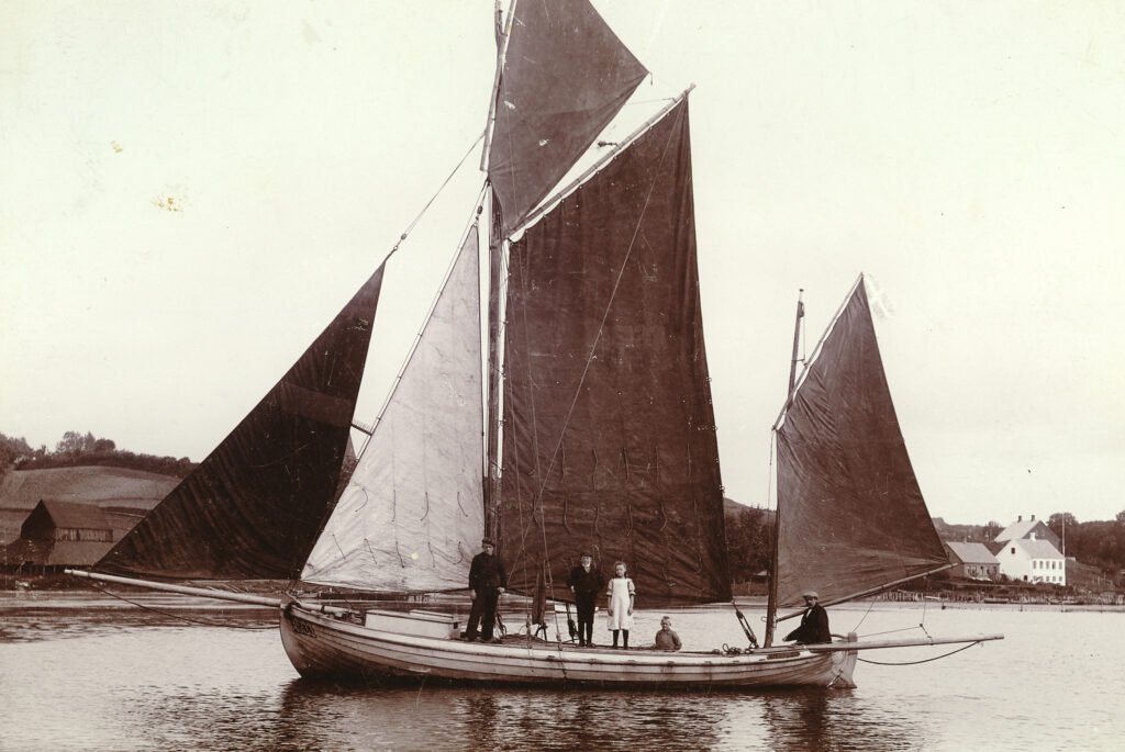
Photo: Maritime Museum of Denmark
Built by F. Mortensen
Photo: Maritime Museum of Denmark
Extant Vessels
I was hosted by Morten Gøthche and Johannes Ambjørnsen at the Viking Ship Museum. Johannes showed me the two original vessels Viktoria and Dan. Viktoria belongs to the museum, and Morten owns Dan. Both were built by the same shipwright as De 13 Søskende.


Author’s photos
Known extent vessels:
| Name | Home Port | Builder | Year | Length | Beam | Draught | Owner |
|---|---|---|---|---|---|---|---|
| Viktoria | Roskilde | Christian Nielsen | 1904 | 26.5 | 8.6 | 3.3 | Viking Ship Museum |
| Dan | Askø | Christian Nielsen | 1908 | 26.8 | 9.3 | 3.3 | Morten Gøthche, Roskilde |
| Mæfikken | Dybvig Haven | Kristian Mortensen | 1917 | 29 | 10 | 5 | Fejø Drivkvaselaug, Fejø |
| Christiane | Dybvig Haven | Carl Nielsen | 1918 | Fejø Drivkvaselaug, Fejø | |||
| Karen | Bogø | Anders Andersen | 1921 | 22 | 8.4 | 3.4 | Bogø Kvase Lag, Bogø |
| Ellen | Kalundborg | Kristian Mortensen | 1922 | 26 | 10 | 3 | Henning Pedersen, Kalundborg |
| Concordia | Udby Vig | Kristian Mortensen | 1927 | 28 | 10 | 3 | Nis Olsen, Holbæk |
Information for Christian Nielsen and Kristian Mortensen drifters is from Gøthche1,p79
Viktoria


Photos: Viking Ship Museum, Roskilde, Denmark
Karen


Photos: Bogø Kvase Lag / Karen af Bogø6
Mæfikken


Christiane


Materials
Fasteners
Dimensions
The nails used on a replica built at the Viking Ship Museum are 65mm long with a square shank 4 mm on each side. The head diameter is unknown. I scaled the image from the website and arrived at ~10 mm.


Photos: Viking Ship Museum, Roskilde, Denmark
Jamestown Distributors sells copper boat nails and provides a table of nail gage to rove diameter and nail head diameter. The ratio of rove diameter to nail head diameter is consistent.
| Rove OD | Head Dia | Ratio |
|---|---|---|
| 7.9375 | 4.191 | 1.894 |
| 9.525 | 5.08 | 1.875 |
| 11.1125 | 5.969 | 1.862 |
| Average | 1.877 |
The diameter of the roves used for the replica was 19 mm. One might therefore presume that the nail head corresponding to a 19 mm rove would be 19 / 1.877 = 10.123 ≈ 10 mm, which is consistent with the dimension scaled from the photograph.
The Crown Nail Company offers Danish Boat Spike Nails made of steel. These have a rectangular shank, the closest size to the copper nails used in the replica being 4mm x 5mm with a 10mm head, also consistent with the scaled image.
The web page describing the construction of the replica eel drifter states that iron nails would have been used at the time De 13 Søskende was constructed. It says that copper was used for leisure craft, but it was not until the 1950’s that traditional boatbuilders also began to build with copper nails. In the pictures I took of Viktoria, built in 1904, one can clearly see that the fasteners are copper. However, it is quite likely that the fasteners were all replaced as part of a restoration.
Despite iron having a yield strength 1.5 that of copper, I’ll be presuming the original iron and modern copper fasteners are of approximately the same dimensions.
Hull Planking
Butt Seams
The lower strakes were made of 2 planks, and the upper strakes of 3 planks1, p16. Of the 10 strakes, how many are considered upper and lower is not clear. I choose based on:
- total length (There is a limit to the length of timber that could be obtained)
- variation in width (more of a board is discarded as this increases)
- required board width to accommodate curvature (wider boards are more expensive and much of the board would be wasted)
The butt joints would traditionally be placed at the frames1, pp16,54, though joining planks between the frames with the use of butt blocks provides more freedom when chosing lumber and makes replacing planks easier. Without seams at the frames, there is less chance of water intrusion and correspondingly less concern over rot in these larger timbers, which would be even more costly and difficult to replace than the planks. Viktoria uses butt blocks, a detail my host was keen to point out (see image below).
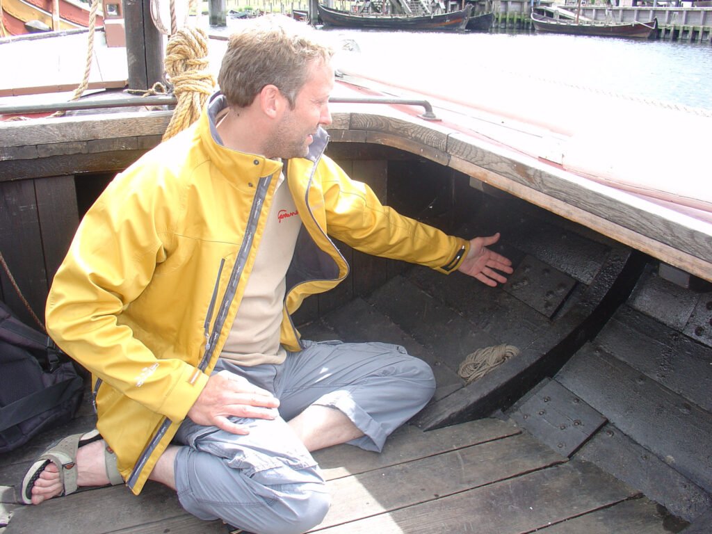
Author’s Photo
Butt blocks were also used in the replica Tumleren1, p54. In his letter to the builder, Nielsen3,p147, Ole J. Strandby requests that his vessel be built with seams at the frames. While the builders of Tumleren were worried about rot at the frames, Mr. Standby was more concerned with rot at the butt blocks. That he bothered to make this specific request could imply that Nielsen was known to use both techniques. I find them to be an interesting detail, and chose to use them for De 13 Søskende.
After installing 3 strakes on each side using the butt block technique, I recieved additional photographs of the model built by Nielsen’s grandson. No butt blocks are visible. It is entirely possible that this detail was simply omitted from the model, and I am not taking it as evidence that butt blocks were not used on De 13 Søskende. Even if originally constructed with seams at the frames, Viktoria and/or De 13 Søskende could have been re-planked during their lifetimes with the use of butt-blocks, so I am not overly worried about the accuracy of including them.
Edge Seams
The planks overlapped by approximately 1-3/8″ and fastened with clinch nails spaced approximately 5-1/2″ apart.3,p110
Wet Well
A series of holes was drilled in the hull planking where it forms a boundary of the wet well1, p18. The note says the holes were small enough to keep eels from escaping, but it does not provide a diameter nor a number or pattern. Nielsen’s model did not shed any light on this aspect, as they seem to be omitted entirely. Eventually, a kind member of the Fejø Drivkvaselaug (Fejø Drift Sailing Club) sent me these photos of Christiane‘s hull. It was stated that the holes appear to be approximately 1/2″.


Photos courtesy of Fejø Drivkvaselaug
Waterline
The waterline was scribed so that the correct trim could be determined even if the paint were worn away1,p22. I will scribe a very light line, which may or may not be visible after painting.
Pancakes
In the time period in which these boats were built, they would celebrate completion of the hull planking with traditional yeast pancakes (‘raised pancakes’)1, p16; 3,p110. I will do the same!
Deck
Planks
Gøthche states that 7″ planks were normal, but to combat leaks due to shrinkage, 5″ planks were sometimes used1, p20. The deck planks drawn for De 13 Søskende show some variation, but are all close to 5″. I’m using a consistent width of 5″ unless it leaves too narrow a strip at the outside. In that case I will widen the center plank(s).
Toe Rail
Gøthche states the toe rails are 3.5″ high before adding the rail cap1,p20. I measure this at only 3″ on the drawings for De 13 Søskende. As he did not seem to imply any variation, I’m inclined to go with the larger dimension, which will allow more room for cutting out the scuppers.
He also points out the existence of a fairlead for the anchor chain cut out of the toe rail on the port bow. This does not show up in the drawings for De 13 Søskende, but I do have a photograph from Viktoria, which shows it reinforced as well.
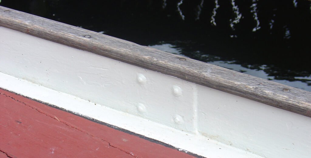
Rub Rail
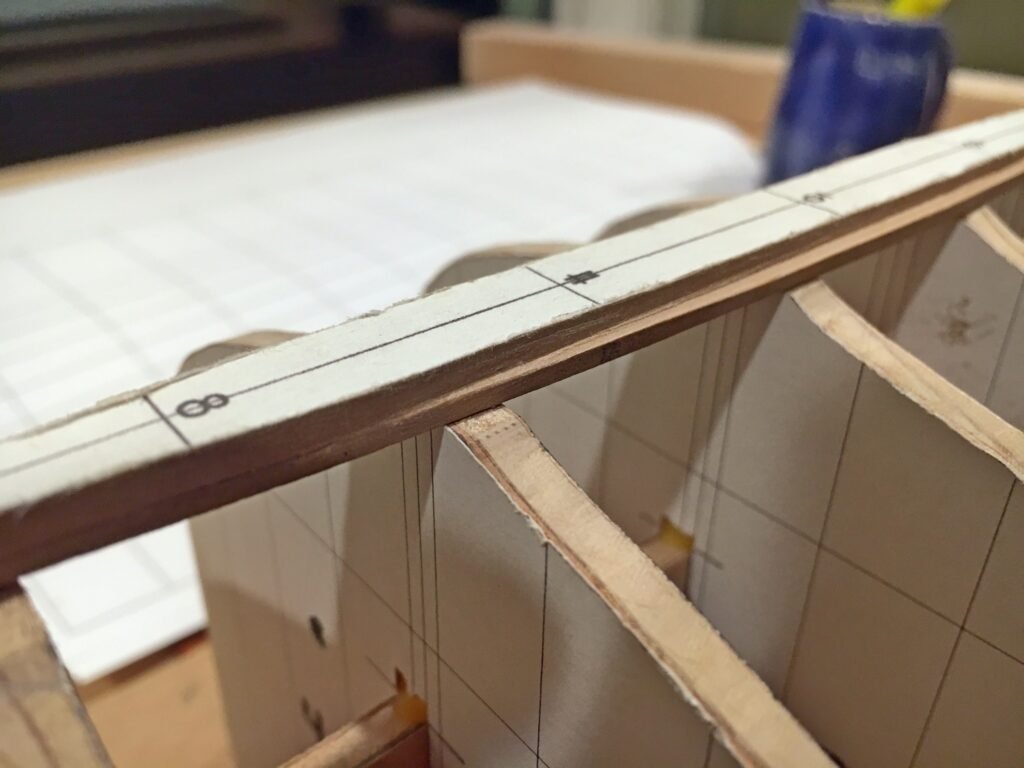
Gøthche states this as 2″ thick, though he may have meant deep1,p20. However, this is called out on the drawings for De 13 Søskende as only 3/4″x7/8″. I’ll see which looks more appropriate when I get to that stage in the model. Note the staggering of the fasteners each side of the midline in the image above.
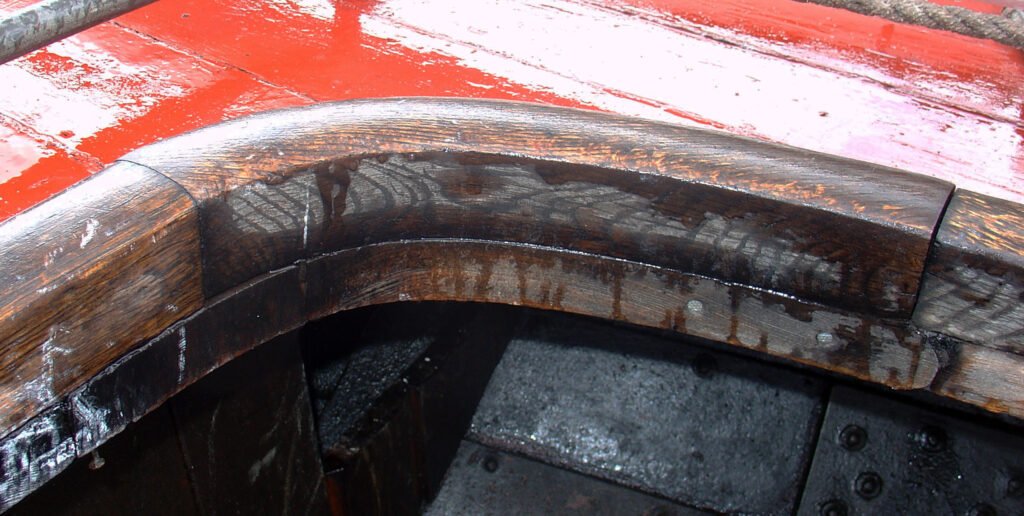
Coamings
Gøthche states this as 2″x2″, rounded over on the top1,p20 for both the large opening and the cockpit at the tiller. I took a photo to show how the tight radius at the corners was handled.
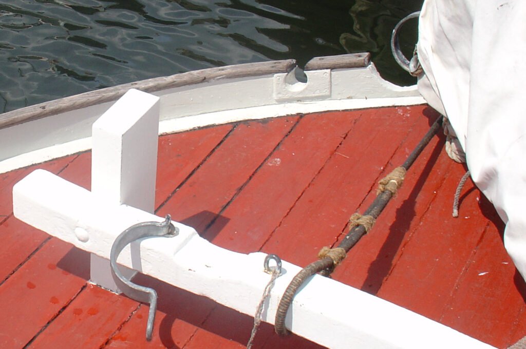
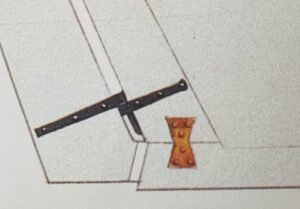
Bitts
There were two common forms of mooring bitts. Dan and Viktoria have two vertical posts attached to a deck beam and extending well below deck. De 13 Søskende has two large wooden cleats. In both cases there was a cross piece between the bitts and cleats, to which the heel of the jib boom was secured.1, p18.


Author’s photo (left). Drawing (right), Maritime Museum of Denmark.
This and the cabin roof were offset several inches to port of the centerline in order to provide more room to work the starboard side, where the net was always set1,p20.
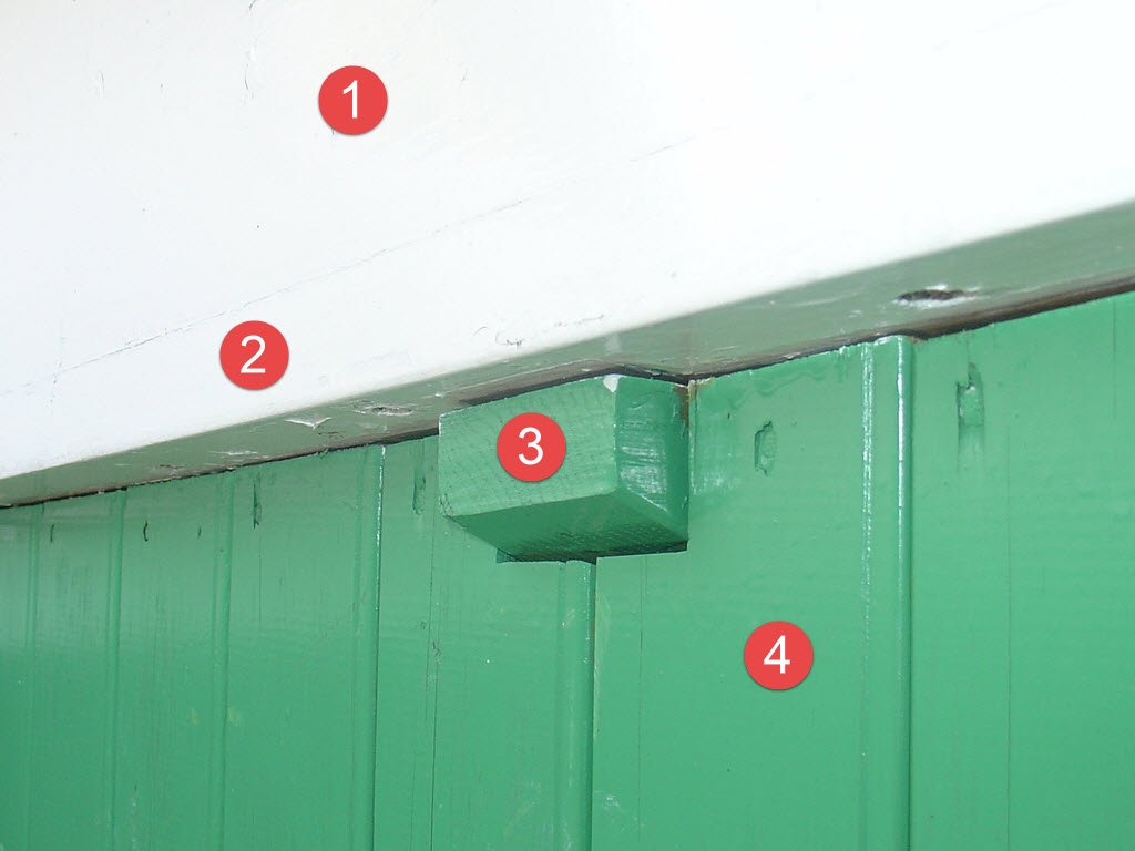
Cabin Roof
Gøtche points out that the cabin roof was laid directly upon the deck and fastened from underneath1,p20. Evidence of this can be seen in a photograph taken from within Viktoria’s cabin, where the nails on the underside of the deck planks are clearly visible. This detail would only be visible when looking up from the cabin floor. I include it nonetheless, as it is mentioned in Gøtche’s book and I choose to document the vessel as thoroughly as possible.
- Side of cabin roof
- Deck plank
- Deck half-beam
- Wall of sleeping cabin or equipment locker
Keel, Frames, and Beams
Keel
The Naval Cutter Alert (Anatomy of the Ship), Goodwin, Peter
A detail pointed out by Gøthche that is not shown in the plans for De 13 Søskende is the hourglass-shaped reinforcement between the keel and sternpost1,p22. Being an inexperienced modeler, I did not know this was a common practice within and outside of Denmark, and would have missed including this feature. But after having seen it mentioned, I recalled the horseshoe-shaped reinforcement at the stem of Alert in the Anatomy of the Ship series. I looked at the back side of the dust jacket to see if there was a reinforcement at the stern. Sure enough there was, hourglass-shaped as well.
Deck Beams
Gøthche states that the deck beams forming the fore and aft ends of the deck opening were 3″x3″ with about 4″ of camber. He goes on to mention a single knee and series of half-beams supporting the side deck, but without mentioning dimensions1,p20. The drawings for De 13 Søskende do not show any variation between the deck beams, knee, or half-beams, which appear rectangular, approximately 2.5″ wide and 2″ deep. I will opt to go with the slightly larger dimensions given by Gøthche for the deck beams.
Forecastle
If I choose to open up the cabin for viewing, the book by Gøthche offers some details that could be included1,p18:
- A square opening on the forward bulkhead of the main space, leading to a smaller space where the boys bunk would be fixed athwartship.
- A removeable hatch on the next bulkhead forward, behind which was stowage space.
- Decorative edging, as photographed on Viktoria
- Bunk on the starboard side, two lockers for clothes and provision on the port
- Space to hang clothes aft of the lockers on the port side
- Small bench on aftermost bulkhead for cooking equipment and other utensils, at the same height as the wet well deck.
- Small benches in front of the lockers and bunk
- Folding table on the foremost bulkhead, with fiddles to prevent crockery from sliding off the edge.
It also points out that on Dan the sailor’s bunk is enclosed, whereas it is open on De 13 Søskende.
Rigging
Shrouds
Mainmast supported by two sets of shrouds of twisted wire, attached with shroud seizings. The mizzen was unstayed1,p28.
Forestay
The forestay was passed through a hole in the stem and seized to the bitts. Alternatively it could be shackled to an eye fitting on the stem1,p28.
Dan and Viktoria both have the forestay led through the stem, as does the model of De 13 Søskende made by Nielsen.
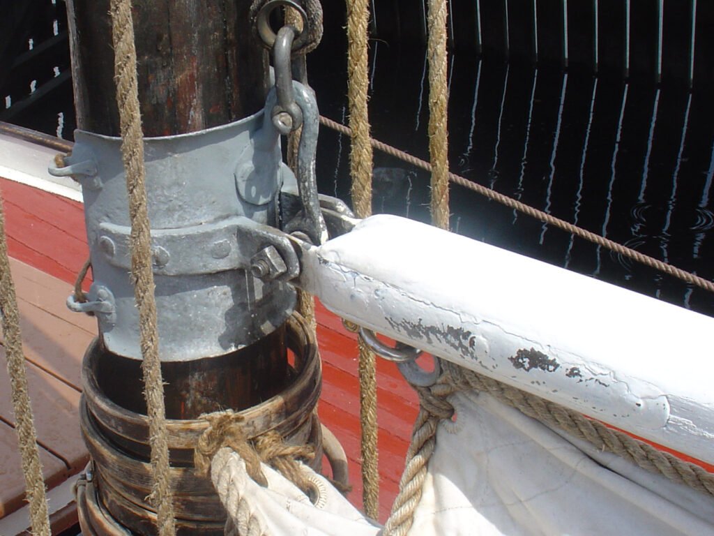
Mainsail Gaff
The mainsail gaff was equipped with a patent parrel, a rotating, bow-shaped fitting that could slide up and down the mast. This fitting made it possible to lower the peak of the gaff all the way to vertical, so that the gaff hung down along the mast, allowing the sail to be furled to the mast1,p28.
Sails
Bands from an original sail from Dan were 53cm, and another sail from another vessel an equivalent width1,p30.
Drifters usually had four reef bands on the mainsail and two on the foresail [staysail]. Only the three lower reef bands were equipped with reef points. The uppermost band was left with reef eyelets only, for loose reef points to be inserted when necessary. The mainsheet was attached to the clew becket with a hook so that it could be easily moved to a grommet on the leech of the sail, inline with the reef band1,p30.
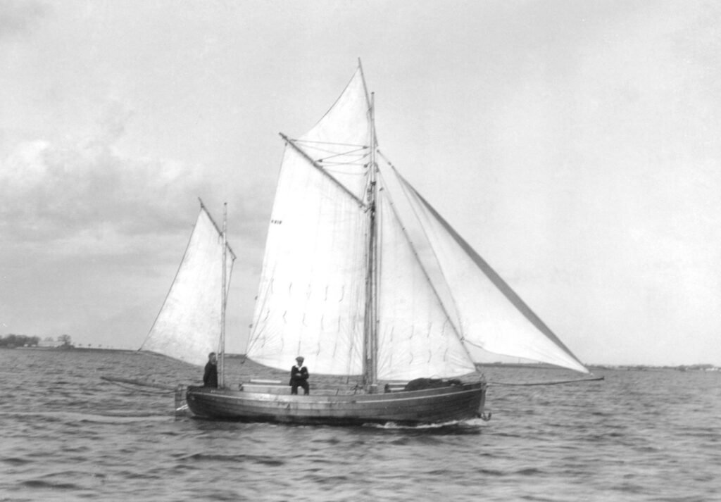
The sails were treated with a mixture of horse fat, ochre, wood tar and water, or with catechu (an extract of acacia [glossary_exclude]bark[/glossary_exclude] imported from the far east). The former would take on a mottled, golden color, as in the right-hand image below. Catechu would become rusty red or brown. The majority of the images I’ve seen (like those of Elisabeths Minde and Haabet shown ealier) are rather dark, implying catechu was more common. The sails shown in the one known photo of De 13 Søskende are rather light, but this photo is later in life after a change in owners, so it is not definitive in selecting a color for the model’s sails. The model by Christian Nielsen is more representative of the time at which it will be modeled, and he chose tan colored sails. This is also not definitive, as he may have simply generalized based on common practice at the time. I would probably be justified in choosing either style, or even a combination. As sails wore out or became damage, a fisherman might purchase whatever was readily available, or perhaps a used item to save money. Refer again to the photo of Haabet, which has dark sails, apart from a light-colored staysail. Choosing such a combination might add more interest to the model and a greater sense of realism – in life, few things are perfect.

Finishes
Below the Waterline
Under the waterline the hull was treated with coal tar1, p22.
Freeboard
The freeboard of most drifters was grey, but some (including De 13 Søskende) were painted Schweinfurt Green1,p22, a.k.a Paris Green, Emerald Green, Vienna Green. This appears to be confirmed by Christian Nielsen’s model.
I did not know about this pigment or how widespread was its use. Unfortunately, it is highly toxic. More on that topic can be found here.
As for the actual hue of Schweifurt Green, the Wikipedia article states “The color of Paris green is said to range from a pale blue green when very finely ground, to a deeper green when coarsely ground.” However, I presume the coarser grind would be more economical and thus more likely to be used for a fishing vessel. I have two shades of Ronan Japan colors, one of which is named ‘Emerald Green’. It is a close match to the old paint can and jar. I also have ‘CP Green Light’, which also looks to be the proper hue, but a shade too dark. Perhaps a mix of the two will yield a good result.


Photo credits. clockwise from upper-left: 1) Wikipedia, 2) Straus Center for Conservation and Technical Studies, Harvard University 3) Utrecht Art Supply 4) Ronan Paints
Rub Rail, Cabin Roof
Normally green1,p22, but vessels from Askø3,p017 were painted brown, as on the extant vessels Dan and Viktoria1,p22. De 13 Søskende was also from Askø, but on Christian Nielsen’s model the cabin roof is green, like the freeboard. I have to decide if I think it more likely Nielsen’s model is accurate or De 13 Søskende actually stuck with local tradition. Since the green freeboard is also a break from the norm, I presume the cabin roof is also, and will paint it green on the model.
Rail Cap
Varnished1,p22.
Deck
Varnished, but the varnish was often mixed with a little ‘English Red‘, a pigment derived from iron oxide1,p22. The RGB color as specified by Wikipedia appears to be a good match for the deck of Dan. Viktoria‘s deck lacks the brownish hue from the iron oxide. Though worn, Dan‘s deck appears rather opaque for a mixture of varnish and paint. I wonder if it is just paint. I may use a wash so that it looks more like a high-solids stain, as seen on many home decks.


Author’s photos.
Launching
In addition to the pancakes served at the completion of hull fastening, another tradition I aim to honor is the post-launching feast, at which coffee, tea, æbleskiver and Fejø-punch would be served1,p24. My wife and I snacked on æbleskiver as we walked around Den Gamle By (the old town) at Christmas time. I searched in vain for the recipe for Fejø-punch until I noticed it in the margin of the book.
Fejø-punch
- 2 litersa of rum
- 1-1/2 bottles of red wine
- 2 pounds sugar
- Cinnamon sticks
- Equal quantities of water and rumb
a) The recipe actually calls for 2 pots of rum, a pot being 0.966 liters. I figured, since my model will be 3% too small, why not over compensate by adding 3.4% too much rum 😉
b) This one confuses me; equal parts water and the mixture above?
Fishing Rig
Here are two images depicting the seine net and its use.


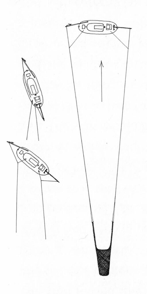
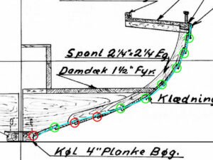
Gøthche gives details about how the boat is configured when drifting. The far right of the image shows the boat drifting directly downwind. He states that when retrieving the net, the boat is pointed into the wind. I assume a few points off, as in the upper-left of this image, so that the boat is not pointed directly into the mouth of the seine. The position shown at the bottom-left depicts the boat drifting slightly astern, which could be achieved by pulling the aft seine line in slightly1,p33.
My intention is to provide a visual indication of the vessel’s historic use and how it functioned by modeling the boat in the process of fishing. The seine is quite large, and when fully deployed it is quite a distance from the vessel, as shown in the diagram. I’ve seen models like this, but only in museums where space is not an issue. To keep the display size reasonable for my home, I can depict it as the seine is being set or taken in. I considered having the net still on the deck, but seriously doubt my ability to model a natural-looking pile of netting. I also doubt that I could well-depict the seized bag full of eels being hauled onto the deck. Doing so would also prevent me from showing the sails set close-hauled, as described below. I think having the sails set in an unusual fashion would make the model more interesting. It seems the best bet, for both size and interest, is to show only the arms of the net, in the water a short distance from the boat, as if it the net has just been let out. The next image is a concept of the display. The rectangle is the display case. The arms of the seine net are at the bottom and the viewer must imagine the rest of the net. I would show the sea floor and a number of eels among grass to convey the quary of the fisherman. A few plaice and a sunken log could be added for interest. I’ve never modeled water before. If trials are successful, the hull would rest within a hole cut in a plexiglass sheet with the water’s surface modeled with acrylics. The wake of the boat moving sideways would further convey the method of drift seining. We shall see if this comes to fruition.
The boat would be sailed “hove-to”, with the mainsail set as usual but the [staysail] set on the windward side, with its clew tied to the foremast shrouds [E]. The jib and mizzen would also be set as well, to balance the boat during its sideward drift.1,p32
The set for the jib and mizzen are not specified as it is for the main and staysail. It appears it would be difficult to bring the mizzen clew to windward, and it seems the boat would be unbalanced if neither that nor the jib is set to windward, with only the staysail aback. So, I presumed the jib clew is also brought to the windward side. This was fortunately confirmed later when I received more images of Mr. Nielsen’s model. He shows the staysail sheet secured to the shroud, as it would only be when hove to. The staysail is set to the same side.


Left: Staysail secured to starboard shroud.
Middle and right: Jib sheet secured on the same side as the staysail.
Original photos: Maritime Museum of Denmark.
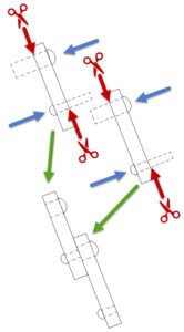
The magenta arrows below indicate how the forces on the boat were balanced – the staysail and jib, being brought to windward, would push the boat aft. The main and mizzen would push it forward.
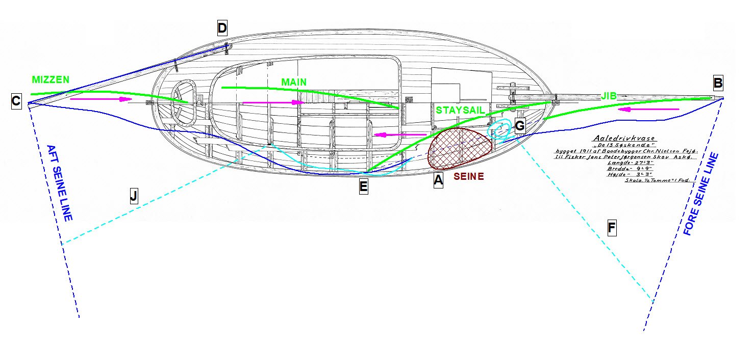
Seine nets were stored on the foredeck to starboard, just forward of the shroud [A]. They would be set from here, paid out from the jib boom forward and the drift boom aft, while the sails were set. …1,p32
Does that mean “while setting the sails” or “with the sails already set”? I presume the net was payed out gradually, to ensure nothing gets tangled. To pay it out gradually, the boat must be making noticeable leeway, if not moving directly sideways. I’m not an experienced sailor, so it’s not clear to me if the staysail would have to be to windward for this, or if the jib to windward would be enough, particularly if the mainsheet is eased to take some power out of that sail. The foot of the jib is rather high, and perhaps would not be in the way at all. It appears the staysail is cut just high enough to work the net while the sail is to windward. It will be easier to envision when the model reaches that stage.
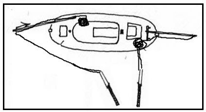
The end of one of the seine lines was fashioned into an eye that could be slipped over the tip of the jib boom [B]. The other line was passed through a hole in the outer end of the drift boom aft [C] and then led to the forward end of the boom, where it was belayed on a cleat [D]1,p32.
Above it was stated that the net was “paid out from the jib boom forward and the drift boom aft.” But if the forward seine line is terminated with an eye, set over the end of the jib boom, it cannot be paid out from there. I presume it is paid out from the foredeck until all the slack is taken out, at which point the boom will take the strain.
On the fore seine line, an additional light line [G] was attached at a little distance out from the boat and made fast on a cleat set into the foredeck [F]. When the haul was over, this line was used to pull the seine line in towards the boat, which now pointed into the wind. A corresponding line was used aft [J].
In the diagram above, the main lines are shown in dark blue, and the lighter lines (G and J), are shown in light cyan. The solid lines show how I imagine they would be before letting out the seine, and the dashed lines as they would be after the net is completely out. Note that the aft line must be led outside the shrouds.
References and Links
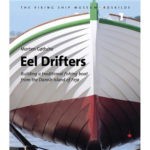
- Eel Drifters, Morten Gøthche, published by the Viking Ship Museum, Roskilde, Denmark, ISBN: 978-87-85180-67-4
Note: Inch dimensions referenced in this source correspond to the Danish ell of 1835. There is a difference of ~3%. - Wooden Boat Designs, Christian Nielsen, Charles Scribner’s Sons, New York, ISBN: 0-684-16432-9, English translation of:
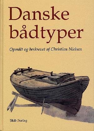
Danske bådtyper : opmålt og beskrevet, Høst & Søns Forlag, 1982 ISBN 87-14-28286-0
Note: Inch dimensions referenced in these two sources correspond to the Danish ell of 1835. There is a difference of ~3%. - Bådebyggerie på Fejø og de Danske Åledrivkvaser, Christian Nielsen
I have provided a rough translation. - DAN og VIKTORIA, to åledrivkvaser, Morten Gøthche
I have provided a rough translation. - The Encyclopedia Britannica: A Dictionary of Arts, Sciences, Volume 27, page 221
- Karen of Bogø (website)
- Replica drifter Tumleren (website)
- Fejø Drifters (website)
- Fejø Boat Building (website)
- Video on eel drifters, Viking Ship Museum, Roskilde
- Drifter Kvasen (website)
- Eels in Culture, Fisheries and Science in Denmark, Suzanne Rindom et al., National Institute for Aquatic Resources / Technical University of Denmark, 2014
More links for me to follow on this page
The Keel

The vessel has a plank keel, meaning that it is much wider than it is deep. The keel varies in width a great deal, but other than a short span at the forward end, it is of constant thickness. Toward midship, the rabbet transforms into an external shelf, forming a “land” for the garboard strake (red circle in image). There is only a bit of rocker in the keel and it curves upward just a small amount to meet the stem. With this small amount of curvature and thickness change, the easiest approach was to
- create a slab for the maximum width and thickness
- cut the width along the length of the keel
- adjust the thickness as needed
- cut the land
- steam and bend it to match the rocker
Well, an easier approach would have been to build it up from three thinner pieces: one for the overall width, one for the width below the land, and another to increase the thickness forward. But I preferred to construct if from a single piece, as with the actual vessel.
Templates
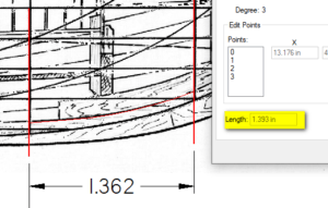
Length of 1.393 is for thin red line along the keel.
Even though there is very little rocker in the keel and only a small amount of curvature at the bow, I went through the process of “unfolding” the keel to create the templates. I imported the sheer plan into SolidEdge 2D and placed a curve along the keel between each pair of stations. The program provides the girth length of the curve (see image to the right). Even between the two forward stations with the most curvature, the difference between the girth and axial lengths was only 1/32″ (2.3%) at model scale, but a little extra accuracy never hurts.
I then imported the half-breadth plan to measure the keel width at each station. “Unfolding” the keel is simply a matter of drawing a series of vertical lines for the keel widths at each station, with the distances between the stations matching the girth lengths taken earler.
I prefer fairing curves by hand, as opposed to using the curve tool in the 2D sketcher, so I printed these lines and then drew curves through the end points of the keel width marks. This was done for the top and bottom of the keel. You can see I was well off the mark for station 3 of the keel top. I could not get a fair curve through that point. I checked my measurement of the drawing, but got the same result. Doubting the keel would have flaired out that abruptly, I went with what looked natural.
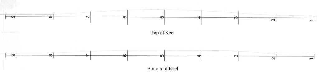
Distances between the vertical lines are the girth lengths of the keel between stations.
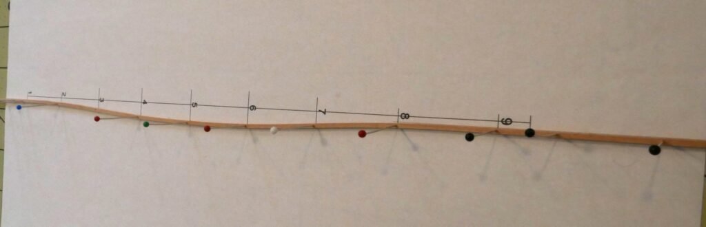
The weights got in the way of drawing the curve.
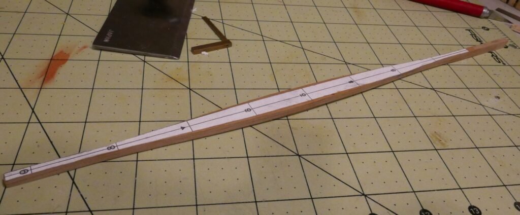
Shaping and Assembly of the Keel
Templates for the top and bottom widths were glued to the plank and the plank cut to the outer-most shape. I then used a home-built thickness sander to remove material in the region of uniform thickness and hand shaped the forward end. To cut the land, I glued a hobby knife blade to a thin piece of wood that I slid along the tabletop, scoring a line at a constant height along the length of the keel. After a light pass on the side, I cut down from the bottom of the keel. This was repeated until the land was cut to the template on the bottom side. It turned out to be a bit of a hatchet job of which I am not too proud. Luckily for me, the hull will be painted so I’ll be able to cover up my rough carving work. The land was not tapered at this point, the variable slope of the land to be determined when installing the garboard plank.
The keel was then steamed and clamped to a bending jig. I was not patient enough and cracked the keel at the forward end by applying too much clamping pressure. Rather than restart, I moved the joint location further aft than indicated in the drawings, with aplogies to Mr. Nielsen for the inaccuracy. Once off the bending jig, I attached the stem and sternpost and roughed in the rabbets, with adjustments to be made while fairing the molds and planking.


The Building Jig
I started by using SolidEdge 2D, to overlay the body plan with the midship construction drawing. I found that the midship body plan line (mostly) passes through the plank lands. So, the body plan is neither the inner (molded) surface nor the outer surface of the hull. Given how relatively thin the planks are, I opted not to make any adjustments for plank thickness.
The building jig is a standard affair, consisting of molds taken from the body plan, mounted upside down on a baseboard. The solid blocks at each end were not part of the original scheme. To bevel the edges of the molds, I use a fairing board fashioned from a strip of wood, double-sided tape, and sandpaper. The bevels will not be correct if you don’t match the shape of the entrance and the run, and I found it impossible to do so without a guide, particularly with the drastic curvature of the rounded stern. So, part way through the beveling process I added the filler at each end.


To shape the filler blocks, I created waterline and body plan templates at 1/4″ intervals. As noted earlier, I made no adjustments for plank thickness when cutting the molds at each station. My stem and stern templates overlapped rabbets by far more than just the plank thickness. I double checked the keel, stem, sternpost and the location of the rabbets, and all closely matched the drawings. I don’t have an explanation for this. Perhaps I should return that piece of paper The University of Michigan gave me declaring I am a Naval Architect [side note: I did work as a Naval Architect for 8 years, but in the Marine Engineering (mechanical) side of the field. I’ve never had to fair lines professionally, but I did get an A+ on my first drawing in NavArch 101.] In the end, I just progressively took off more material until a fairing batten met the stem and sternpost rabbets. I used the oversized templates as a guide to make sure the amount of additional material removed was proportional at each waterline, giving the expected overall shape. Note the small metal setup block in the top-right image below. It is holding the inboard end of the template on top of wooden spacers at the proper height, to keep it from sagging or rising up. Once the port side was to my satisfaction, I added tabs to the templates to mark the final shape. I traced this onto new templates to avoid the small error that would occur from flipping the template over to the starboard side. This new template needs a shim of the same thickness, as illustrated in the bottom-left image. I recognize the difference may have been undetectable if I hadn’t bothered with this correction, but it’s best to not let errors compound.
A quick note about fairing boards. Many people use rigid sanding sanding blocks to fair frames. Others use emory boards. I make mine from a piece of sandpaper adhered with double-sided tape to a strip of wood. Being of the same material (wood, if not the same species), it closely mimics how the planking will bend. For initial fairing, the board had sandpaper nearly the entire length. For fine tuning, a shorter length of sandpaper is bordered by card stock of approximately the same thickness. The cardstock allows the fairing board to ride at the same level on the filler blocks or adjacent molds without sanding them further. The extent of the sandpaper is marked on the back side of the fairing board so one can avoid altering an area considered finished.


Planking
Pattern
The construction drawing shows where the bottom of each plank should be amidships, at the stem, and at the sternpost. There is no one path between these points, so I used battens to lay out the run for each plank. I started with the garboard and next four bottom strakes. I then did the sheer strake and several adjacent planks. These have the most curvature and it was paramount to match the shape of the planks as they met the sternpost, particularly at the top. Once satisfied with the lower and upper strakes, I filled in the gap ensuring a nice transition between the two sections.
My initial means of holding the battens in position while making adjustments was rubber bands stretched between nails on the molds. You can see holes where the nails had been. The rubber bands kept slipping off the beveled edges, so I glued a temporary cleat to each mold near the batten and/or turn of the bilge. This worked adequately (not well) for strakes close to the keel, where the tension on the rubber band pressed directly downward on the battens. There was not enough pressure after the turn of the bilge, so I switched to the spring clamps shown below. Once in position, I pinned the batten in place and moved to the next. There were some final adjustments necessary – sometimes a little sideways nudge on a pin was enough. Other times repositioning the pin was necessary, but not enough to avoid the existing hole, which would bring it back to the original position. In cases like this I could sometimes drive the pin in at an angle rather than filling in the hole in the mold and replacing the batten. Once finalized, I etched the positions on the molds.


Garboard and Plank Keel
The fairing battens can be used as guides to bevel the edges of the previous plank. In the case of the garboard strake, it is the plank keel that needs beveling. I am not proud of the hatchet job I made of the rabbet or the side of the keel.


Fasteners
In my mind, the most important aspect of a ship model is scale fidelity. Scale should be consistent throughout a model and as accurate as possible. Further, being oversized is more obvious than being undersized. Therefore, my rule of thumb is, if a detail would appear missing to the naked eye, I include it on the model. However, if I cannot represent that detail without it being oversized, I leave it off.
“To the naked eye” includes peering close up with young eyes or a good pair of readers. From a normal viewing distance, the detail may be invisible or barely perceptible. But if perceptible at all, the viewer will be drawn in for a closer look. This is part of what has often been described as a “compelling impression“. I also like to take close-up photographs of my models, for documentation and to spot areas for improvement. So, if I can, I may even model beyond what is visible to the naked eye.
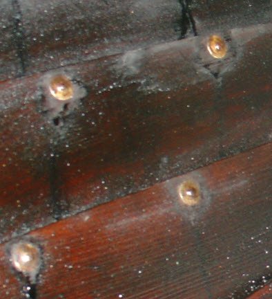
With that in mind, I needed to decide whether or not to simulate the fasteners on this model. I started with the question, how visible were they on the actual vessel? As you can see from this image of Viktoria, the roves are clearly visible.
And on the exterior (below, left), the round-headed nails are also easily seen. However, the flat-headed nails on Dan (below, right) are more or less invisible at a similar distance. At least, I presume they are flat-headed nails. On closer inspection, they almost appear to be round-headed nails driven deeper, with the margins slightly filled with paint. Regardless, the appearance is of a flat-headed nail, as used on the replica Tumleren (see Research→Fasteners), so I will refer to them as such from this point forward.
All three boats (Dan, Viktoria, and De 13 Søskende) were built by Christian Nielsen. There is no indication of which style was used for De 13 Søskende, nor have I been able to determine if round-headed and/or flat-headed nails were more common in the period. Therefore, I had to choose a style. I ultimately settled on the round-headed nails for the sake of creating a more compelling impression that, as far as I can tell, does not diminish historical accuracy.
That choice was largely based on whether or not I could represent them accurately. I had some small nails on hand that were close enough to the proper size for the head to represent the rove and the shank to represent a flat headed nail. I inserted a few on a piece of wood and determined the nail head (rove on the model) would indeed be easily discernable to the naked eye and should be included on the model. I felt it was likely the shank (nail head on the model) would still be slightly visible even after sanding it flush with the hull surface and painting. Even if completely hidden, it would be in keeping with scale fidelity for flat-headed nails. Unfortunately, I did not have enough of them, so I searched for alternatives.
At scale, the rove diameter should be 0.031″ (~0.8mm) and the nail head should be 0.016″ (~0.4mm). I considered scale rivets sold by Model Motorcars, which are 0.4mm in diameter with a 0.85mm head. This was an extremely good match (the roves would only be 6% oversized) and the only thing I could find that was even remotely close to the proper size. However, with well over 1000 rivets, the expense would have been significant. I instead settled on a technique attributed to Michael Bezverhny on the Dominoff Workshop YouTube channel. A blunt edge is ground onto a metal object. When run back and forth over a short piece of copper wire, the wire mushrooms out until it is separated. The first piece cut away has a head and a shank and looks more or less like a round-headed nail. Each subsequent piece second has two heads, like a dumbbell, but can be cut in half to produce two nails. Note: an old dinner knife was used for the video and initially I had used the same. The handle was deeper than the blade, making it difficult to use, so I ground the bevel on the back side of my 6″ straight edge.
Using this technique, the head size is just barely larger than the shank. If the wire diameter is chosen to accurately simulate the rove, the shank would be much too large to simulate the nail head. Thus, the copper wire cannot be driven through both planks to represent both the nail head and the rove. Two wires of different diameters must be inserted opposite one another. The wire on the outside could be cut flush to simulate a flat-headed nail, or the “Bezverhny method” could be used to simulate a round-headed nail.
The difficulty in using this technique for a rove or round-headed nail is that the length of the shank can only be the plank thickness (0.036″) or less. Any more than this and installing a wire on one side would drive out the wire on the opposite side. If they were offset slightly, the shanks could be made slightly less than twice the plank thickness. The offset would be imperceptible. However, there would still be the difficulty of not drilling all the way through and I found guiding and pressing a 0.072″ long nail into a predrilled hole nearly impossible. When gripped with forceps, none of the shank remains exposed, such that it can inserted in the hole. Attempting to grip a nail by the head resulted in it slipping out and being flung across the room. I tried some pointy tweezers, small enough to grip the shank and still have a small length exposed, but they did not have enough grip to drive the wire into the hole.
Everything I described in the previous paragraph presumes the fasteners are installed after the strakes are glued together. If inserted before joining the planks, the shank can be as long as is needed to easily press it through the hole. The ends can then be snipped off and sanded flush before gluing the planks together. Once I realized this, the technique appeared to be a viable option – both frugal and very effective, albeit time consuming. With the variety of wire gages available, it is applicable to a wide range of nail sizes.
To get as close as possible to the rove diameter without going over, I have used 22 ga copper wire. This is nominally 0.0253″, but by my calipers it is closer to 0.024″. After using the technique mentioned above, the head of the wire ranges between 0.0275″ and 0.031″. I discarded anything below 0.0285″ so there is less than a -10% error. For the nail heads I used 26 ga wire, which is nominally 0.0159″, but also measures a bit smaller on my calipers at 0.0150″. I got far more consistent results with this wire, perhaps due to a difference in hardness rather than the diameter itself. Each simulated nail head is very close to 0.017″, or +6%. As mentioned previously, I would rather be a bit undersized than oversized, but the next smaller wire size did not give acceptable results. It tended to separate before mushrooming out enough to form a head, and when it did work it was too far from the desired size. I decided being 6% over was acceptable.
For the most part, a friction fit seemed to be sufficient. But I widened a few holes where I was a bit clumsy in the installation. I decided to glue all of them. I was reluctant to use cyanoacrylate (CA), as it discolors the wood and does not allow for any mistakes. Wood glue does nothing to bond copper to wood. An internet search led to me deciding on liquid hide glue. It does not provide the strength of CA, but it is better than nothing. It does not discolor the wood at all, and after a couple of minutes the consistency is similar to rubber cement and the excess is easily scraped away.


Spiling
There is very little about lapstrake construction mentioned in ship model how-to books. Spiling is covered in nearly all of them, but the approach must be adapted slightly for this method of hull construction. Here are some notes about how I approached it.
[add notes about creating initial templates]
It is very difficult to sight both edges of the plank to be fitted and to hold it in place for measuring necessary adjustments and (later) for gluing. My solution was to glue temporary cleats on each frame of the jig where they had been marked using the fairing battens. First, that edge of the plank is faired so that it lies along the cleats without any edge bending. The edge overlapping the previous plank is then faired as shown in the following images.


A note on step 6: In these images, I am using the thickest unused feeler gage as a backstop. I later found it easier to press the plank edge and feeler gages against something heavy. Make it heavy enough that it will not move, tall enough for plank and feeler gages to bear against, and narrow enough not to interfere with the concave edge of the plank. If you have one, the prong of a full-size drafting duck would work nicely. The miniature ones seen here would be too light.